Showing posts with label VPNv4. Show all posts

Wednesday, April 11, 2018

MPLS Inter AS Option 2 / Option B VPNv4 BGP Exchange

In this post we'll take a look at Option B which is a VPNv4 eBGP peering in the global table to connect the 2 MPLS SPs together. The purpose of the VPNv4 AFI BGP peering is to easily exchange VPNv4 traffic with each other. Just like in Option C, we'll lay out the steps that are needed to get the configuration working.

What needs to be implemented ahead of time is the Intra AS VPN setup, IGP/LDP, MP-BGP, VRFs/PE-CE routing. 
1. VPNv4 eBGP peering between the ASBRs.
2. Allow VPNv4 routes. We'll be using the IOS "no bgp default route-target filter" and XR "retain route-target all". This will just allow whatever route targets to be learned.
Option B is a pretty straightforward configuration overall. Not as configuration intensive as Option A or C. The Intra AS configuration is in place already. We have to configure the eBGP VPNv4 peering and disable the default route-target filter and enable retain route-target all under BGP.

With that said, unlike Option C and CSC, we'll have 3 separate LSPs in our setup. I will break that down once the traceroute is complete.


R5
router bgp 50693
 bgp log-neighbor-changes
 no bgp default ipv4-unicast
 no bgp default route-target filter
 neighbor 100.64.56.6 remote-as 2
 neighbor 192.0.2.8 remote-as 50693
 neighbor 192.0.2.8 update-source Loopback0
 !
 address-family ipv4
 exit-address-family
 !
 address-family vpnv4
  neighbor 100.64.56.6 activate
  neighbor 100.64.56.6 send-community extended
  neighbor 192.0.2.8 activate
  neighbor 192.0.2.8 send-community extended
  neighbor 192.0.2.8 next-hop-self
 exit-address-family


R6
router bgp 2
 bgp log-neighbor-changes
 no bgp default ipv4-unicast
 no bgp default route-target filter
 neighbor 100.64.56.5 remote-as 50693
 neighbor 100.64.166.16 remote-as 50693
 neighbor 192.0.2.23 remote-as 2
 neighbor 192.0.2.23 update-source Loopback0
 !
 address-family ipv4
 exit-address-family
 !
 address-family vpnv4
  neighbor 100.64.56.5 activate
  neighbor 100.64.56.5 send-community extended
  neighbor 100.64.166.16 activate
  neighbor 100.64.166.16 send-community extended
  neighbor 192.0.2.23 activate
  neighbor 192.0.2.23 send-community extended
  neighbor 192.0.2.23 next-hop-self
 exit-address-family


XR6
router bgp 50693
 address-family vpnv4 unicast
  retain route-target all
 !
 neighbor 100.64.166.6
  remote-as 2
  address-family ipv4 labeled-unicast
   route-policy RPL_LOCAL_PREF in
   route-policy RPL_EBGP_PEERINGS out
  !
  address-family vpnv4 unicast
   route-policy RPL_EBGP_PEERINGS in
   route-policy RPL_EBGP_PEERINGS out

With the configuration in place now, we'll verify.

R5#show bgp vpnv4 unicast all summary | b Neighbor
Neighbor        V           AS MsgRcvd MsgSent   TblVer  InQ OutQ Up/Down  State/PfxRcd
100.64.56.6     4            2     141     143       17    0    0 02:03:22        2
192.0.2.8       4        50693     152     150       17    0    0 02:10:42        4

R5#show bgp vpnv4 unicast all | b Network
     Network          Next Hop            Metric LocPrf Weight Path
Route Distinguisher: 1:1 (default for vrf CSC)
 *>i 100.64.21.0/24   192.0.2.1                0    100      0 i
 *>  100.64.114.0/24  100.64.56.6                            0 2 65004 i
 *>i 100.64.165.0/24  192.0.2.15               0    100      0 65016 i
 *>i 192.0.2.2/32     192.0.2.1                0    100      0 65002 i
 *>  192.0.2.4/32     100.64.56.6                            0 2 65004 i
 *>i 192.0.2.16/32    192.0.2.15               0    100      0 65016 i


R6#sh bgp vpnv4 unicast all summary | b Neighbor
Neighbor        V           AS MsgRcvd MsgSent   TblVer  InQ OutQ Up/Down  State/PfxRcd
100.64.56.5     4        50693     145     142       15    0    0 02:04:46        4
100.64.166.16   4        50693     127     140       15    0    0 02:01:12        4
192.0.2.23      4            2     135     150       15    0    0 02:08:25        2

R6#sh bgp vpnv4 unicast all | b Network
     Network          Next Hop            Metric LocPrf Weight Path
Route Distinguisher: 1:1 (default for vrf CSC)
 *   100.64.21.0/24   100.64.166.16                          0 50693 i
 *>                   100.64.56.5                            0 50693 i
 *>i 100.64.114.0/24  192.0.2.11               0    100      0 65004 i
 *   100.64.165.0/24  100.64.166.16                          0 50693 65016 i
 *>                   100.64.56.5                            0 50693 65016 i
 *   192.0.2.2/32     100.64.166.16                          0 50693 65002 i
 *>                   100.64.56.5                            0 50693 65002 i
 *>i 192.0.2.4/32     192.0.2.11               0    100      0 65004 i
 *   192.0.2.16/32    100.64.166.16                          0 50693 65016 i
 *>                   100.64.56.5                            0 50693 65016 i


RP/0/0/CPU0:XR6#show bgp vpnv4 unicast summary | b Neighbor
Wed Apr 11 21:16:57.455 UTC
Neighbor        Spk    AS MsgRcvd MsgSent   TblVer  InQ OutQ  Up/Down  St/PfxRcd
100.64.166.6      0     2     186     169       17    0    0 02:03:57          2

RP/0/0/CPU0:XR6#show bgp vpnv4 unicast | b Network
Wed Apr 11 21:17:21.413 UTC
   Network            Next Hop            Metric LocPrf Weight Path
Route Distinguisher: 1:1
*>i100.64.21.0/24     192.0.2.1                0    100      0 i
*> 100.64.114.0/24    100.64.166.6                           0 2 65004 i
* i                   192.0.2.5                0    100      0 2 65004 i
*>i100.64.165.0/24    192.0.2.15               0    100      0 65016 i
*>i192.0.2.2/32       192.0.2.1                0    100      0 65002 i
*> 192.0.2.4/32       100.64.166.6                           0 2 65004 i
* i                   192.0.2.5                0    100      0 2 65004 i
*>i192.0.2.16/32      192.0.2.15               0    100      0 65016 i

Processed 6 prefixes, 8 paths


Now that we have seen that the routes have been propagated and learned. We'll focus on the end to end connectivity the 3 LSPs.

R2#traceroute 192.0.2.4 source lo0 num
Type escape sequence to abort.
Tracing the route to 192.0.2.4
VRF info: (vrf in name/id, vrf out name/id)
  1 100.64.21.1 [AS 50693] 5 msec 3 msec 4 msec
  2 100.64.17.7 [MPLS: Labels 26/44 Exp 0] 9 msec 8 msec 10 msec
  3 100.64.75.5 [MPLS: Label 44 Exp 0] 31 msec 31 msec 31 msec
  4 100.64.56.6 [MPLS: Label 28 Exp 0] 30 msec 31 msec 32 msec
  5 100.64.106.10 [MPLS: Labels 17/57 Exp 0] 21 msec 32 msec 31 msec
  6 100.64.114.11 [AS 65004] [MPLS: Label 57 Exp 0] 19 msec 19 msec 72 msec
  7 100.64.114.4 [AS 65004] 49 msec *  8 msec


R2#traceroute 192.0.2.4 source lo0 num
LSP1
  1 100.64.21.1 [AS 50693] 5 msec 3 msec 4 msec
  2 100.64.17.7 [MPLS: Labels 26/44 Exp 0] 9 msec 8 msec 10 msec
  3 100.64.75.5 [MPLS: Label 44 Exp 0] 31 msec 31 msec 31 msec

LSP2
  4 100.64.56.6 [MPLS: Label 28 Exp 0] 30 msec 31 msec 32 msec

LSP3
  5 100.64.106.10 [MPLS: Labels 17/57 Exp 0] 21 msec 32 msec 31 msec
  6 100.64.114.11 [AS 65004] [MPLS: Label 57 Exp 0] 19 msec 19 msec 72 msec
  7 100.64.114.4 [AS 65004] 49 msec *  8 msec

The reason for the 3 LSPs, three separate next hops.
LSP1 - ingress PE to egress PE/ASBR
LSP2 - egress PE/ASBR to ingress PE/ASBR
LSP3 - ingress PE/ASBR to egress PE

Sunday, February 5, 2017

CCIE SPv4 - MPLS Traffic Engineering - TE Attributes - Auto Bandwidth

Software versions:
IOS XE 15.5
IOS XR 5.3

The topology for this demo:
This post will be a look at "auto-bandwidth or auto-bw". The idea behind this feature is make better use of bandwidth allocation for a tunnel rather than just give the tunnel all the bandwidth that the "bandwidth" command specified. Leveraging just the bandwidth definitely works and has it's use but if you specify 100 Mbps as the bandwidth reservation and the average bandwidth use is 10 Mbps, the tunnel is being under utilized. Auto BW would take a look at the utilization over a given period of time, 5 minutes by default, and allocate the highest bandwidth seen in that period of time to the tunnel. 

interface Tunnel7
 ip unnumbered Loopback0
 load-interval 60
 tunnel mode mpls traffic-eng
 tunnel destination 192.168.1.6
 tunnel mpls traffic-eng priority 7 7
 tunnel mpls traffic-eng bandwidth 6
 tunnel mpls traffic-eng affinity 0x0 mask 0x0
 tunnel mpls traffic-eng path-option 1 dynamic
 tunnel mpls traffic-eng auto-bw frequency 600 max-bw 100 min-bw 10


R3#show mpls traffic-eng tunnels tunnel 7 | sec auto-bw
    auto-bw: (600/328) 0  Bandwidth Requested: 10
          Samples Missed 0: Samples Collected 0

The auto-bw (600/xxx) means that every 600 seconds, the tunnel will get checked for bandwidth optimization. The "0" next to it would have the bandwidth allocated. Bandwidth requested is 10 here, for 10 Kbps. The drawback in my lab is that the platform limit is 100000 bps. 

R3#sh ip rsvp reservation filter session-type 7 tunnel-id 7
Destination     Tun Sender      TunID LSPID Next Hop        I/F      Fi Serv BPS
192.168.1.6     192.168.1.3     7     7     10.14.3.14      Gi1.143  SE LOAD 6K

As you can see the 6 Kbps of bandwidth reservation are signaled and working. However, since we are requesting less than the minimal limit that the auto-bw option can support, we won't actually see any modification. 

Thanks for stopping by!
Rob Riker, CCIE #50693

CCIE SPv4 - MPLS Traffic Engineering - TE Attributes - Path Options

Software versions:
IOS XE 15.5
IOS XR 5.3

The topology for this demo:
In this post we will take a look at the "path option" feature, which essentially determines how the TE tunnel will calculate its path. We can be either really "lazy" or really involved in this process, lazy with using the dynamic option and letting RSVP go out and find the shortest path and pretty much use IGPs path and call it a day. We could also use the explicit path option which allows us to have more control over where the traffic goes. We haven't covered PE to P LSPs yet for things like H-VPLS TE support, what we'll focus on here is R3 to XR3 and XR3 to R3 LSP signalling. The dynamic path option is the easiest and has been used so far in all of our testing so no reason to really break that out here. Let's focus on the explicit path and start there.

There are several ways to "code" the path, the "ip explicit-path" is the primary way. This method allows us to be really specific or be rather general. General in the sense I can give the path certain IPs that must be in the path and the others I may not care about. Other times I could give per interface path IPs and be really specific. Using the "loose" keyword allow us to specify the node we want to go through, but not necessarily how we go through. The strict keyword pretty much says you have to go through it. 

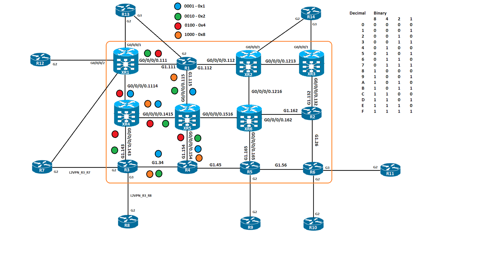
Our demo will start with leveraging the loose option and just build a TE tunnel path from R3 to XR3. The path we will take is XR4 to XR1 to R1 to XR5 to XR6 to R2 to XR3, not exactly direct but we want to exercise our capabilities. 

R3
ip explicit-path name LOOSE_TO_XR3 enable
 next-address loose 192.168.1.14
 next-address loose 192.168.1.11
 next-address loose 192.168.1.1
 next-address loose 192.168.1.15
 next-address loose 192.168.1.16
 next-address loose 192.168.1.2
 next-address loose 192.168.1.13
interface Tunnel4
 ip unnumbered Loopback0
 tunnel mode mpls traffic-eng
 tunnel destination 192.168.1.13
 tunnel mpls traffic-eng affinity 0x0 mask 0x0
 tunnel mpls traffic-eng path-option 1 explicit name LOOSE_TO_XR3


R3#show mpls traffic-eng tunnels tunnel 4

Name: R3_t4                               (Tunnel4) Destination: 192.168.1.13
  Status:
    Admin: up         Oper: up     Path: valid       Signalling: connected
    path option 1, type explicit LOOSE_TO_XR3 (Basis for Setup, path weight 1)

RSVP Path Info:
      My Address: 10.14.3.3
      Explicit Route: 10.14.3.14 192.168.1.14 192.168.1.11* 192.168.1.1*
                      192.168.1.15* 192.168.1.16* 192.168.1.2* 192.168.1.13*

Explicit Route: 10.14.3.3 10.14.3.14 10.14.15.14 10.14.15.15
                    10.15.16.15 10.15.16.16 10.16.2.16 10.16.2.2
                    10.13.2.2 10.13.2.13 192.168.1.13

As you can see above, we have configured our explicit path to use the TE ID of the nodes in the path to XR3. The * you see next to each of the router IDs is the indication of a loose path. The explicit path noted below the RSVP path is the actual path that will be taken from R3 to XR3. 

Now let's take a look at an strict explicit path.

R3
ip explicit-path name STRICT_TO_XR3 enable
 next-address 192.168.1.4
 next-address 192.168.1.15
 next-address 192.168.1.1
 next-address 192.168.1.12
 next-address 192.168.1.13
interface Tunnel5
 ip unnumbered Loopback0
 tunnel mode mpls traffic-eng
 tunnel destination 192.168.1.13
 tunnel mpls traffic-eng priority 4 4
 tunnel mpls traffic-eng affinity 0x0 mask 0x0
 tunnel mpls traffic-eng path-option 1 explicit name STRICT_TO_XR3

R3#show mpls traffic-eng tunnels tunnel 5

Name: R3_t5                               (Tunnel5) Destination: 192.168.1.13
  Status:
    Admin: up         Oper: up     Path: valid       Signalling: connected
    path option 1, type explicit STRICT_TO_XR3 (Basis for Setup, path weight 5)

RSVP Path Info:
      My Address: 10.3.4.3
      Explicit Route: 10.3.4.4 10.15.4.4 10.15.4.15 10.1.15.15
                      10.1.15.1 10.1.12.1 10.1.12.12 10.12.13.12
                      10.12.13.13 192.168.1.13

Explicit Route: 10.14.3.3 10.14.3.14 10.14.15.14 10.14.15.15
                    10.15.16.15 10.15.16.16 10.16.2.16 10.16.2.2
                    10.13.2.2 10.13.2.13 192.168.1.13

As you can see, the RSVP path is configured to use R4 to XR5 to R1 to XR2 to XR3. I don't have a static route or other traffic to tunnel mapping mechanism in place for this TE tunnel, so this path is simply a different output to show you the difference. The Other explicit route is the route that falls under the "Shortest Unconstrained Path" in the network, basically, this is the LDP path in the network. The RSVP path is the one that will be followed.


The next option is the "identifier" where state which devices we want the TE tunnel to go through.

ip explicit-path identifier 1 enable
 next-address 192.168.1.4
 next-address 192.168.1.5
 next-address 192.168.1.6
 next-address 192.168.1.2
 next-address 192.168.1.16
 next-address 192.168.1.15
 next-address 192.168.1.14
 next-address 192.168.1.11
 next-address 192.168.1.1
 next-address 192.168.1.12
 next-address 192.168.1.13
interface Tunnel6
 ip unnumbered Loopback0
 tunnel mode mpls traffic-eng
 tunnel destination 192.168.1.13
 tunnel mpls traffic-eng affinity 0x0 mask 0x0
 tunnel mpls traffic-eng path-option 1 explicit identifier 1

ip route 192.168.1.13 255.255.255.255 Tunnel6

R3#show mpls traffic-eng tunnels tunnel 6

Name: R3_t6                               (Tunnel6) Destination: 192.168.1.13
  Status:
    Admin: up         Oper: up     Path: valid       Signalling: connected
    path option 1, type explicit 1 (Basis for Setup, path weight 11)

RSVP Path Info:
      My Address: 10.3.4.3
      Explicit Route: 10.3.4.4 10.4.5.4 10.4.5.5 10.5.6.5
                      10.5.6.6 10.2.6.6 10.2.6.2 10.16.2.2
                      10.16.2.16 10.15.16.16 10.15.16.15 10.14.15.15
                      10.14.15.14 10.11.14.14 10.11.14.11 10.1.11.11
                      10.1.11.1 10.1.12.1 10.1.12.12 10.12.13.12
                      10.12.13.13 192.168.1.13

This path hits every router in the MPLS core, intentionally configured to show you it could be done that way. I also configured a static route pointing towards XR3 to use Tunnel 6. 

R3# traceroute mpls traffic-eng tunnel 6
Type escape sequence to abort.
  0 10.3.4.3 MRU 1500 [Labels: 28 Exp: 0]
L 1 10.3.4.4 MRU 1500 [Labels: 42 Exp: 0] 10 ms
L 2 10.4.5.5 MRU 1500 [Labels: 36 Exp: 0] 3 ms
L 3 10.5.6.6 MRU 1500 [Labels: 26 Exp: 0] 5 ms
L 4 10.2.6.2 MRU 1500 [Labels: 24013 Exp: 0] 4 ms
L 5 10.16.2.16 MRU 1500 [Labels: 24014 Exp: 0] 10 ms
L 6 10.15.16.15 MRU 1500 [Labels: 24010 Exp: 0] 17 ms
L 7 10.14.15.14 MRU 1500 [Labels: 24026 Exp: 0] 15 ms
L 8 10.11.14.11 MRU 1500 [Labels: 40 Exp: 0] 18 ms
L 9 10.1.11.1 MRU 1500 [Labels: 24014 Exp: 0] 11 ms
L 10 10.1.12.12 MRU 1500 [Labels: implicit-null Exp: 0] 17 ms
! 11 10.12.13.13 17 ms

Let's do a little recursion to make sure we still know how to figure out where the TE label gets allocated and why.

R3#show ip route 192.168.1.13
Routing entry for 192.168.1.13/32
  Known via "static", distance 1, metric 0 (connected)
  Routing Descriptor Blocks:
  * directly connected, via Tunnel6
      Route metric is 0, traffic share count is 1

R3#sh ip cef 192.168.1.13 detail
192.168.1.13/32, epoch 2, flags [attached]
  local label info: global/30
  3 RR sources [non-eos indirection, heavily shared]
  attached to Tunnel6

R3#sh mpls forwarding-table labels 30 detail
Local      Outgoing   Prefix           Bytes Label   Outgoing   Next Hop
Label      Label      or Tunnel Id     Switched      interface
30         Pop Label  192.168.1.13/32  0             Tu6        point2point
        MAC/Encaps=18/22, MRU=1500, Label Stack{28}, via Gi1.34
        000C2924DCA2000C29062644810000228847 0001C000
        No output feature configured

We will first look at the RIB, we see that traffic to XR3s loopback will be sent out Tunnel 6, if we do a CEF lookup we can see that a local global label of 30 has been allocated to that prefix. We can use that now in the MPLS lookup and see that 30 is the local label, label 28 is the outgoing label and it points out Tunnel 6.

Let's checkout XR3 now, we can also configure path options on XR3. They are almost identical in XR so I'll only show you the TE tunnel to R3 I created to show some basic verification against.

XR3
explicit-path identifier 1
 index 1 next-address strict ipv4 unicast 192.168.1.2
 index 2 next-address strict ipv4 unicast 192.168.1.6
 index 3 next-address strict ipv4 unicast 192.168.1.5
 index 4 next-address strict ipv4 unicast 192.168.1.4
 index 5 next-address strict ipv4 unicast 192.168.1.3
interface tunnel-te2
 ipv4 unnumbered Loopback0
 destination 192.168.1.3
 affinity ignore
 path-option 1 explicit identifier 1

RP/0/0/CPU0:XR3#show mpls traffic-eng tunnels 2
Sun Feb  5 03:18:33.883 UTC


Name: tunnel-te2  Destination: 192.168.1.3  Ifhandle:0x780
  Signalled-Name: XR3_t2
  Status:
    Admin:    up Oper:   up   Path:  valid   Signalling: connected

Node hop count: 5
  Hop0: 10.13.2.2
  Hop1: 10.2.6.2
  Hop2: 10.2.6.6
  Hop3: 10.5.6.6
  Hop4: 10.5.6.5
  Hop5: 10.4.5.5
  Hop6: 10.4.5.4
  Hop7: 10.3.4.4
  Hop8: 10.3.4.3
  Hop9: 192.168.1.3

We can see that the tunnel was successfully signalled and the path was built. Slightly different output from IOS but it still makes sense. I created a static route to point to R3 for verification purposes.

router static
 address-family ipv4 unicast
  192.168.1.3/32 tunnel-te2

RP/0/0/CPU0:XR3#sh cef 192.168.1.3 detail | in label
Sun Feb  5 03:20:18.416 UTC
     local label 24013      labels imposed {ImplNull}

RP/0/0/CPU0:XR3#show mpls traffic-eng forwarding p2p tunnel-id 2 detail
Sun Feb  5 03:21:07.423 UTC
P2P tunnels:

Tunnel ID:    2 LSP ID:    2 Destination:     192.168.1.3 Ctype:  7
  Source:    192.168.1.13 Ext Tun ID:    192.168.1.13
  Output: Gi0/0/0/0.132     Next Hop: 10.13.2.2       Output Label: 29
  Input:  -                 Prev Hop: None            Local Label:  24028


RP/0/0/CPU0:XR3#traceroute mpls traffic-eng tunnel-te 2 lsp active
Type escape sequence to abort.

  0 10.13.2.13 MRU 1500 [Labels: 29 Exp: 0]
L 1 10.13.2.2 MRU 1500 [Labels: 37 Exp: 0] 0 ms
L 2 10.2.6.6 MRU 1500 [Labels: 43 Exp: 0] 10 ms
L 3 10.5.6.5 MRU 1500 [Labels: 29 Exp: 0] 10 ms
L 4 10.4.5.4 MRU 1500 [Labels: implicit-null Exp: 0] 0 ms
! 5 10.3.4.3 10 ms

The routing table has R3s loopback pointed out Tunnel 2, the CEF output states that local label 24013 will be used. IOS XR has a separate but equally important traffic-eng forwarding table for us to leverage, we see that label 29 will be used for outbound forwarding. A MPLS trace proves that label 29 will be used as the transport label to R3.

As you can see, the path option is very handy in situations like this, being able to manipulate the forwarding is key in modern networks. 

Thanks for stopping by!
Rob Riker, CCIE #50693

Wednesday, January 25, 2017

CCIE SPv4 - MPLS Traffic Engineering - TE Attributes - Affinity Lists and Maps

Software versions:
IOS XE 15.5
IOS XR 5.3

The topology for this demo:
In this post we will be expanding on the previous post, where we explored using affinity values to influence the path we took for TE paths. Well we are using some scalability options, the "list" in IOS and the "map" in XR. 

The list in IOS acts very much like a "prefix-list" does, it matches some value we specify and then is used as a "true" or "false" mechanism on the TE tunnel for RSVP PCALC. The idea is to create the list with a given set of variables, the affinity, bandwidth and priority are a few of the options. Once the list is created it can be called by the "path option" feature under the TE interface. I have created 3 of them, the first is a single color match, BLUE in this case, the second is a 2 color match, GREEN and BLUE and the third is a 2 color, match RED but not ORANGE. These attribute lists are then called by the TE tunnels.

R3
mpls traffic-eng lsp attributes DUAL_COLOR
 affinity 0x11 mask 0x11
mpls traffic-eng lsp attributes DUAL_COLOR_MATCH_ONLY_ONE
 affinity 0x100 mask 0x1100
mpls traffic-eng lsp attributes SINGLE_COLOR
 affinity 0x1 mask 0x1
!
interface Tunnel2
 ip unnumbered Loopback0
 tunnel mode mpls traffic-eng
 tunnel destination 192.168.1.11
 tunnel mpls traffic-eng path-option 2 dynamic attributes SINGLE_COLOR
!
interface Tunnel3
 ip unnumbered Loopback0
 tunnel mode mpls traffic-eng
 tunnel destination 192.168.1.11
 tunnel mpls traffic-eng path-option 3 dynamic attributes DUAL_COLOR
!
interface Tunnel4
 ip unnumbered Loopback0
 tunnel mode mpls traffic-eng
 tunnel destination 192.168.1.11
 tunnel mpls traffic-eng path-option 4 dynamic attributes DUAL_COLOR_MATCH_ONLY_ONE


R3#sho mpls traffic-eng tunnels brief | b P2P
P2P TUNNELS/LSPs:
TUNNEL NAME                      DESTINATION      UP IF     DOWN IF   STATE/PROT
R3_t1                            192.168.1.1      -         Gi1.143   up/up
R3_t2                            192.168.1.11     -         Gi1.34    up/up
R3_t3                            192.168.1.11     -         unknown   up/down
R3_t4                            192.168.1.11     -         Gi1.143   up/up

As you can see, Tunnel 1, 2 and 4 are up, Tunnel 3, there was an issue and didn't come up. That is was an affinity match logic that wasn't correct or could have been no match in the network was found, either could be true. 

The "map" option is unique to XR and has some of those same options, it is meant to be an easier way to work with affinity. Mapping a human readable string to an affinity value, then using that string to identify affinity at the interface level. I only have 2 interfaces so I only have 2 affinity maps.

mpls traffic-eng
 interface GigabitEthernet0/0/0/0.111
  attribute-names GREEN
 !
 interface GigabitEthernet0/0/0/0.1114
  attribute-names BLUE
 !
 affinity-map BLUE bit-position 0
 affinity-map GREEN 0x10

interface tunnel-te1
 ipv4 unnumbered Loopback0
 logging events all
 destination 192.168.1.3
 affinity 0x1 mask 0x1
 path-option 10 dynamic
!
interface tunnel-te2
 ipv4 unnumbered Loopback0
 logging events all
 destination 192.168.1.3
 affinity include GREEN
 path-option 2 dynamic
!
interface tunnel-te3
 ipv4 unnumbered Loopback0
 logging events all
 destination 192.168.1.3
 affinity include BLUE
 path-option 10 dynamic

RP/0/0/CPU0:XR1#show mpls  traffic-eng tunnels brief
Wed Jan 25 22:29:01.598 UTC

                     TUNNEL NAME         DESTINATION      STATUS  STATE
                      tunnel-te1         192.168.1.3          up  up
                      tunnel-te2         192.168.1.3          up  up
                      tunnel-te3         192.168.1.3          up  up
                           R3_t1         192.168.1.1          up  up
                           R3_t2        192.168.1.11          up  up
                           R3_t4        192.168.1.11          up  up
Displayed 3 (of 3) heads, 1 (of 1) midpoints, 2 (of 2) tails
Displayed 3 up, 0 down, 0 recovering, 0 recovered heads

As you can see, all three tunnels are up and operational. 

Now that we have everything  up and running, it's time to verify the tunnels. We'll start on IOS and then check XR.

R3#$n detail filter session-type 7 tunnel-id 4 | in Label|GigabitEthernet1.
  Next Hop: 10.14.3.14 on GigabitEthernet1.143
  Label: 24006 (outgoing)
R3#$n detail filter session-type 7 tunnel-id 2 | in Label|GigabitEthernet1.
  Label: 1 (outgoing)
  Next Hop: 10.3.4.4 on GigabitEthernet1.34
  Label: 19 (outgoing)

As you can see, the RSVP TE label applied has 2, 19 towards R4 and 24006 towards XR4. 


R3#show mpls  forwarding-table labels 31 detail | in Label
Local      Outgoing   Prefix           Bytes Label   Outgoing   Next Hop
Label      Label      or Tunnel Id     Switched      interface
31         Pop Label  192.168.1.11/32  0             Tu2        point2point
        MAC/Encaps=18/22, MRU=1500, Label Stack{19}, via Gi1.34
           Pop Label  192.168.1.11/32  488           Tu4        point2point
        MAC/Encaps=18/22, MRU=1500, Label Stack{24006}, via Gi1.143

You can see in the mpls forwarding table output, that we are pointing out both tunnels with 2 different label values.

R3#sh ip cef 192.168.1.11 detail
192.168.1.11/32, epoch 2, flags [attached], per-destination sharing
  local label info: global/31
  2 RR sources [non-eos indirection, heavily shared]
  attached to Tunnel2
  attached to Tunnel4

The CEF table also shows that.

R3#traceroute mpls traffic-eng tunnel 2
Type escape sequence to abort.
  0 10.3.4.3 MRU 1500 [Labels: 19 Exp: 0]
L 1 10.3.4.4 MRU 1500 [Labels: 24003 Exp: 0] 10 ms
L 2 10.15.4.15 MRU 1500 [Labels: 24004 Exp: 0] 6 ms
L 3 10.14.15.14 MRU 1500 [Labels: implicit-null Exp: 0] 3 ms
! 4 10.11.14.11 10 ms


R3#traceroute mpls traffic-eng tunnel 4
Type escape sequence to abort.
  0 10.14.3.3 MRU 1500 [Labels: 24006 Exp: 0]
L 1 10.14.3.14 MRU 1500 [Labels: implicit-null Exp: 0] 10 ms
! 2 10.11.14.11 9 ms

When you do an MPLS trace, for each tunnel, they take different paths, which is the desired result based on the affinity values leveraged for the tunnels

R8#traceroute vrf BGP 12.12.12.12 source 8.8.8.8 num
Type escape sequence to abort.
Tracing the route to 12.12.12.12
VRF info: (vrf in name/id, vrf out name/id)
  1 83.0.0.3 4 msec 1 msec 2 msec
  2 10.3.4.4 [MPLS: Labels 19/24025 Exp 0] 11 msec 10 msec 12 msec
  3 10.15.4.15 [MPLS: Labels 24003/24025 Exp 0] 9 msec 16 msec 23 msec
  4 10.14.15.14 [MPLS: Labels 24004/24025 Exp 0] 20 msec 19 msec 21 msec
  5 10.11.14.11 [MPLS: Label 24025 Exp 0] 23 msec 19 msec 21 msec
  6 112.0.0.12 21 msec *  15 msec

We do a trace route and see that TE tunnel 2 gets used. 


XR
RP/0/0/CPU0:XR1#sh rsvp reservation session-type lsp-p2p detail destination 192.168.1.3 | in "Label|Gi0/0/0/0.|TunID"

Wed Jan 25 23:23:58.193 UTC
RESV: IPv4-LSP Session addr: 192.168.1.3. TunID: 1. LSPId: 5.
 Input adjusted interface: Gi0/0/0/0.1114. Input physical interface: Gi0/0/0/0.1114.
  Labels: Outgoing downstream: 24005.
RESV: IPv4-LSP Session addr: 192.168.1.3. TunID: 2. LSPId: 2.
 Input adjusted interface: Gi0/0/0/0.111. Input physical interface: Gi0/0/0/0.111.
  Labels: Outgoing downstream: 33.
RESV: IPv4-LSP Session addr: 192.168.1.3. TunID: 3. LSPId: 2.
 Input adjusted interface: Gi0/0/0/0.1114. Input physical interface: Gi0/0/0/0.1114.
  Labels: Outgoing downstream: 24009.

Here we can see that the RSVP RESV labels have been populated which indicates that the affinity values configured were able to be matched on.


RP/0/0/CPU0:XR1#show mpls traffic-eng forwarding detail p2p | in "Tunnel|Label$
Wed Jan 25 23:25:39.136 UTC
  Backup Tunnel: No backup available
Tunnel ID:    1 LSP ID:    5 Destination:     192.168.1.3 Ctype:  7
  Output: Gi0/0/0/0.1114    Next Hop: 10.11.14.14     Output Label: 24005
  Input:  -                 Prev Hop: None            Local Label:  24002
  Backup Tunnel: No backup available
Tunnel ID:    2 LSP ID:    2 Destination:     192.168.1.3 Ctype:  7
  Output: Gi0/0/0/0.111     Next Hop: 10.1.11.1       Output Label: 33
  Input:  -                 Prev Hop: None            Local Label:  24005
  Backup Tunnel: No backup available
Tunnel ID:    3 LSP ID:    2 Destination:     192.168.1.3 Ctype:  7
  Output: Gi0/0/0/0.1114    Next Hop: 10.11.14.14     Output Label: 24009
  Input:  -                 Prev Hop: None            Local Label:  24006
  Backup Tunnel: No backup available

The MPLS TE forwarding table hows that tunnel ID 2 uses label 33 and tunnel ID 3 uses 24009. 

RP/0/0/CPU0:XR1#sh cef 192.168.1.3 detail | in label
Wed Jan 25 23:26:28.422 UTC
     local label 24003      labels imposed {ImplNull}
     local label 24003      labels imposed {ImplNull}
     local label 24003      labels imposed {ImplNull}


RP/0/0/CPU0:XR1#sh route 192.168.1.3
Wed Jan 25 23:27:00.410 UTC

Routing entry for 192.168.1.3/32
  Known via "static", distance 1, metric 0 (connected)
  Installed Jan 25 22:10:47.853 for 01:16:12
  Routing Descriptor Blocks
    directly connected, via tunnel-te1
      Route metric is 0
    directly connected, via tunnel-te2
      Route metric is 0
    directly connected, via tunnel-te3
      Route metric is 0
  No advertising protos.


RP/0/0/CPU0:XR1#traceroute mpls traffic-eng tunnel-te 2
Type escape sequence to abort.

  0 10.1.11.11 MRU 1500 [Labels: 33 Exp: 0]
L 1 10.1.11.1 MRU 1500 [Labels: 24004 Exp: 0] 10 ms
L 2 10.1.15.15 MRU 1500 [Labels: 17 Exp: 0] 10 ms
L 3 10.15.4.4 MRU 1500 [Labels: implicit-null Exp: 0] 10 ms
! 4 10.3.4.3 1 ms

We trace MPLS for TE 2, we see label 33 as the first label, that will be important later on when we do the CE to CE trace. 

RP/0/0/CPU0:XR1#traceroute mpls traffic-eng tunnel-te 3
Type escape sequence to abort.

  0 10.11.14.11 MRU 1500 [Labels: 24009 Exp: 0]
L 1 10.11.14.14 MRU 1500 [Labels: 24006 Exp: 0] 0 ms
L 2 10.14.15.15 MRU 1500 [Labels: 23 Exp: 0] 0 ms
L 3 10.15.4.4 MRU 1500 [Labels: implicit-null Exp: 0] 10 ms
! 4 10.3.4.3 10 ms

We do the same trace for TE3 and we see label 24009 as the first label, this could be construed as a backup path since it is not used in the path between XR1 and R3.

R12#traceroute vrf BGP 8.8.8.8 source 12.12.12.12 num
Type escape sequence to abort.
Tracing the route to 8.8.8.8
VRF info: (vrf in name/id, vrf out name/id)
  1 112.0.0.11 3 msec 1 msec 1 msec
  2 10.1.11.1 [MPLS: Labels 33/52 Exp 0] 10 msec 8 msec 7 msec
  3 10.1.15.15 [MPLS: Labels 24004/52 Exp 0] 27 msec 31 msec 38 msec
  4 10.15.4.4 [MPLS: Labels 17/52 Exp 0] 77 msec 17 msec 11 msec
  5 83.0.0.3 [MPLS: Label 52 Exp 0] 11 msec 9 msec 13 msec
  6 83.0.0.8 23 msec *  12 msec

We can see that label 33 is used for TE2 in this output and not TE3. I haven't found any documentation that indicates why it works this way, but if you were to disable TE 2, TE 3 would be used instead. I shutdown TE 2.

R12#traceroute vrf BGP 8.8.8.8 source 12.12.12.12 num
Type escape sequence to abort.
Tracing the route to 8.8.8.8
VRF info: (vrf in name/id, vrf out name/id)
  1 112.0.0.11 4 msec 1 msec 1 msec
  2 10.11.14.14 [MPLS: Labels 24009/52 Exp 0] 12 msec 8 msec 10 msec
  3 10.14.15.15 [MPLS: Labels 24006/52 Exp 0] 29 msec 31 msec 31 msec
  4 10.15.4.4 [MPLS: Labels 23/52 Exp 0] 33 msec 28 msec 31 msec
  5 83.0.0.3 [MPLS: Label 52 Exp 0] 15 msec 16 msec 15 msec
  6 83.0.0.8 21 msec *  14 msec

TE 3 is now used. 

Bringing TE 2 backup, a new outlabel is allocated.

RP/0/0/CPU0:XR1#sh mpls traffic-eng forwarding
Wed Jan 25 23:47:52.084 UTC
P2P tunnels:

Tunnel ID                  Ingress IF     Egress IF      In lbl  Out lbl Backup
-------------------------- -------------- -------------- ------- ------- -------
192.168.1.3 1_396          Gi0/0/0/0.1114  Gi0/0/0/0.111 24001   3       unknown
192.168.1.11 1_5                        - Gi0/0/0/0.1114 24002   24005   unknown
192.168.1.11 2_3                        -  Gi0/0/0/0.111 24005   42      unknown
192.168.1.11 3_2                        - Gi0/0/0/0.1114 24006   24009   unknown

Displayed 3 tunnel heads, 1 label P2P rewrites
Displayed 0 tunnel heads, 0 label P2MP rewrites

Before it was label 33, now it is label 42.

Thanks for stopping by!
Rob Riker, CCIE #50693