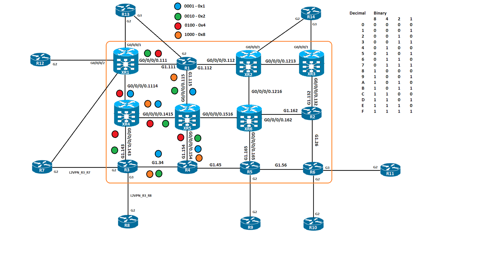
Segment Routing or SR is another labeling mechanism on IOS XR. Most people are familiar with LDP or Label Distribution Protocol for allocating labels the PE and P loopbacks and their connected links. LDP requires the network to maintain a level state equal to the size of the network, if there are only a few routers making up the core, the level of state is pretty low.
The purpose of SR is to control the label allocation that the PE and P routers will use for their loopbacks and the transit links. The key difference between SR and LDP is SR allocates the label to the loopback interface. LDP does not do this, static labeling is supported but configuration intensive. SR uses a dedicated block of labels, the SRGB with a range of 16000-23999.
LDP is deployed along side of IGP but as a different process, IGP needs to be converged before LDP converges or micro loops can occur.
SR is configured under the IGP process for both OSPF and IS-IS. The SR labels are propagated inside of the IS-IS TLVs and OSPF Opaque LSAs.
There are 2 different label allocations, the loopback of the P or PE router and the connected links between the P and PE routers.
The loopback label is called the "Prefix SID" or Prefix Segment Identifier.
The transit label is called the "Adjacency SID" or Adjacency Segment Identifier.
The Prefix SID comes from the 16000-23999 label range, the SRGB.
The Adjacency SID comes from the dynamic label range 24000-1048575.
The only thing that changes in the MPLS L3VPN deployment here is SR is the labeling technique, VRFs, MP-BGP, VRF Aware BGP PE-CE and IGP routing are still needed. The above IOS routers, R1-R4 R1 is ASN 101, R2 is ASN 102 and so forth. The ASN in the core is ASN1. XR6 is a RR to the PE routers.
The configuration and verification outputs are below.
XR1
router ospf 1
area 0
segment-routing forwarding mpls
segment-routing mpls
interface Loopback0
prefix-sid absolute 16021
!
interface GigabitEthernet0/0/0/0.112
!
interface GigabitEthernet0/0/0/0.115
XR2
router ospf 1
area 0
segment-routing forwarding mpls
segment-routing mpls
interface Loopback0
prefix-sid absolute 16022
!
interface GigabitEthernet0/0/0/0.112
!
interface GigabitEthernet0/0/0/0.123
!
interface GigabitEthernet0/0/0/0.126
XR3
router ospf 1
area 0
segment-routing forwarding mpls
segment-routing mpls
interface Loopback0
prefix-sid absolute 16023
!
interface GigabitEthernet0/0/0/0.123
!
interface GigabitEthernet0/0/0/0.134
!
interface GigabitEthernet0/0/0/0.137
XR4
router ospf 1
area 0
segment-routing forwarding mpls
segment-routing mpls
interface Loopback0
prefix-sid absolute 16024
!
interface GigabitEthernet0/0/0/0.134
!
interface GigabitEthernet0/0/0/0.148
XR5
router ospf 1
area 0
segment-routing forwarding mpls
segment-routing mpls
interface Loopback0
prefix-sid absolute 16025
!
interface GigabitEthernet0/0/0/0.115
!
interface GigabitEthernet0/0/0/0.156
XR6
router ospf 1
area 0
segment-routing forwarding mpls
segment-routing mpls
interface Loopback0
prefix-sid absolute 16026
!
interface GigabitEthernet0/0/0/0.126
!
interface GigabitEthernet0/0/0/0.156
!
interface GigabitEthernet0/0/0/0.167
XR7
router ospf 1
area 0
segment-routing forwarding mpls
segment-routing mpls
interface Loopback0
prefix-sid absolute 16027
!
interface GigabitEthernet0/0/0/0.137
!
interface GigabitEthernet0/0/0/0.167
!
interface GigabitEthernet0/0/0/0.178
XR8
router ospf 1
area 0
segment-routing forwarding mpls
segment-routing mpls
interface Loopback0
prefix-sid index 28
!
interface GigabitEthernet0/0/0/0.148
!
interface GigabitEthernet0/0/0/0.178
XR8 is running 5.3 XR code, so the "absolute" option isn't supported, Index and absolute do the same thing, index just calls the label value that will get added to 16000 where absolute defines it completely.
RP/0/0/CPU0:XR1#sh mpls interfaces detail
Wed May 9 19:17:00.751 UTC
Interface GigabitEthernet0/0/0/0.112:
LDP labelling not enabled
LSP labelling not enabled
MPLS enabled
Interface GigabitEthernet0/0/0/0.115:
LDP labelling not enabled
LSP labelling not enabled
MPLS enabled
RP/0/0/CPU0:XR2#show mpls interfaces detail
Wed May 9 19:18:20.711 UTC
Interface GigabitEthernet0/0/0/0.112:
LDP labelling not enabled
LSP labelling not enabled
MPLS enabled
Interface GigabitEthernet0/0/0/0.123:
LDP labelling not enabled
LSP labelling not enabled
MPLS enabled
Interface GigabitEthernet0/0/0/0.126:
LDP labelling not enabled
LSP labelling not enabled
MPLS enabled
As you can see, LDP is not being used here, Segment Routing is.
R1 and R2 have now peered with the SP and advertised their loopbacks into BGP.
R1#sh ip route bgp | b Gateway
Gateway of last resort is not set
192.0.2.0/32 is subnetted, 2 subnets
B 192.0.2.2 [20/0] via 100.64.101.11, 10:18:02
R2#sh ip route bgp | b Gateway
Gateway of last resort is not set
192.0.2.0/32 is subnetted, 2 subnets
B 192.0.2.1 [20/0] via 100.64.103.14, 10:18:48
Now we'll do some trace routes to see how Segment Routing will look different than what LDP will look. NOTE - BGP VPNv4 is still used to allocate labels for customer learned routes, these labels are pulled from the global dynamic label pool.
R2#traceroute 192.0.2.1 source loopback 0 numeric
Type escape sequence to abort.
Tracing the route to 192.0.2.1
VRF info: (vrf in name/id, vrf out name/id)
1 100.64.103.14 23 msec 14 msec 8 msec
2 100.64.134.13 [MPLS: Labels 16021/24004 Exp 0] 107 msec 92 msec 91 msec
3 100.64.123.12 [MPLS: Labels 16021/24004 Exp 0] 99 msec 97 msec 100 msec
4 100.64.112.11 [MPLS: Label 24004 Exp 0] 99 msec 85 msec 88 msec
5 100.64.101.1 89 msec * 110 msec
The 16021/24004 is the 2 label stack we would normally see with LDP, the top label, the transport label, 16021 wouldn't be in the range of 16000-23999.
In this case, the label 16021 isn't LDP allocating labels arbitrarily, this label value is configured on XR1 on the loopback interface and propagated to the other P/PE routers inside of OSPF Opaque LSAs. All of the routers in the core know that to reach XR1 via a labeled path, they must use label 16021 to get there.
We'll take the next several outputs and examine them to breakdown how we the label values above were allocated and understand where they fit in.
Let's see what routes we received in from XR1 via the RR of XR6.
RP/0/0/CPU0:XR4#sh bgp vpnv4 unicast neighbors 192.0.2.26 routes | b Network
Wed May 9 19:31:25.218 UTC
Network Next Hop Metric LocPrf Weight Path
Route Distinguisher: 1:1 (default for vrf A)
*>i192.0.2.1/32 192.0.2.21 0 100 0 101 i
Processed 1 prefixes, 1 paths
We can see that we learned 192.0.2.1 from 192.0.2.21, let's expand that to see what label value VPNv4 applied.
RP/0/0/CPU0:XR4#sh bgp vrf A 192.0.2.1/32
Wed May 9 19:25:24.652 UTC
BGP routing table entry for 192.0.2.1/32, Route Distinguisher: 1:1
Versions:
Process bRIB/RIB SendTblVer
Speaker 4 4
Last Modified: May 9 09:00:02.407 for 10:25:22
Paths: (1 available, best #1)
Advertised to CE peers (in unique update groups):
100.64.103.2
Path #1: Received by speaker 0
Advertised to CE peers (in unique update groups):
100.64.103.2
101
192.0.2.21 (metric 4) from 192.0.2.26 (192.0.2.21)
Received Label 24004
Origin IGP, metric 0, localpref 100, valid, internal, best, group-best, import-candidate, imported
Received Path ID 0, Local Path ID 1, version 4
Extended community: RT:1:1
Originator: 192.0.2.21, Cluster list: 192.0.2.26
Source AFI: VPNv4 Unicast, Source VRF: A, Source Route Distinguisher: 1:1
We see that label 24004 was allocated by VPNv4 for the 192.0.2.1/32 route advertised by XR1. We have the VPN label, now we need to know what to configure as the transport label.
RP/0/0/CPU0:XR4#sh route 192.0.2.21
Wed May 9 19:34:21.986 UTC
Routing entry for 192.0.2.21/32
Known via "ospf 1", distance 110, metric 4, labeled SR, type intra area
Installed May 8 22:23:31.979 for 21:10:50
Routing Descriptor Blocks
100.64.134.13, from 192.0.2.21, via GigabitEthernet0/0/0/0.134
Route metric is 4
No advertising protos.
We see that the route was learned via OSPF intra area propagation, more importantly, labeled SR is propagated as well.
RP/0/0/CPU0:XR4#show cef 192.0.2.21
Wed May 9 19:36:06.659 UTC
192.0.2.21/32, version 16, internal 0x1000001 0x81 (ptr 0xa12b3a74) [1], 0x0 (0xa12994f4), 0xa28 (0xa150d140)
Updated May 8 22:23:32.049
local adjacency 100.64.134.13
Prefix Len 32, traffic index 0, precedence n/a, priority 1
via 100.64.134.13/32, GigabitEthernet0/0/0/0.134, 9 dependencies, weight 0, class 0 [flags 0x0]
path-idx 0 NHID 0x0 [0xa0f592a4 0x0]
next hop 100.64.134.13/32
local adjacency
local label 16021 labels imposed {16021}
Checking the CEF table we can see that both the imposed label and the local label are both 16021. Imposed means that 16021 will be used to forward these packets through the core.
RP/0/0/CPU0:XR4#show mpls forwarding labels 16021
Wed May 9 19:38:12.840 UTC
Local Outgoing Prefix Outgoing Next Hop Bytes
Label Label or ID Interface Switched
------ ----------- ------------------ ------------ --------------- ------------
16021 16021 SR Pfx (idx 21) Gi0/0/0/0.134 100.64.134.13 5628
This is a prefix SID that is applied to XR1's loopback. It is both the local label and the outgoing label.
RP/0/0/CPU0:XR4#sh ospf database opaque-area adv-router 192.0.2.21
Wed May 9 19:39:44.484 UTC
OSPF Router with ID (192.0.2.24) (Process ID 1)
Type-10 Opaque Link Area Link States (Area 0)
LS age: 926
Options: (No TOS-capability, DC)
LS Type: Opaque Area Link
Link State ID: 4.0.0.0
Opaque Type: 4
Opaque ID: 0
Advertising Router: 192.0.2.21
LS Seq Number: 80000027
Checksum: 0x8ceb
Length: 52
Router Information TLV: Length: 4
Capabilities:
Graceful Restart Helper Capable
Stub Router Capable
All capability bits: 0x60000000
Segment Routing Algorithm TLV: Length: 1
Algorithm: 0
Segment Routing Range TLV: Length: 12
Range Size: 8000
SID sub-TLV: Length 3
Label: 16000
LS age: 664
Options: (No TOS-capability, DC)
LS Type: Opaque Area Link
Link State ID: 7.0.0.1
Opaque Type: 7
Opaque ID: 1
Advertising Router: 192.0.2.21
LS Seq Number: 80000027
Checksum: 0xc5ee
Length: 44
Extended Prefix TLV: Length: 20
Route-type: 1
AF : 0
Flags : 0x40
Prefix : 192.0.2.21/32
SID sub-TLV: Length: 8
Flags : 0x0
MTID : 0
Algo : 0
SID Index : 21
Looking at the bolded parts of the OSPF Opaque LSA, we see that the Prefix SID begins at 16000 and carries for 8000 which ranges from 16000 - 23999. Below that we see the Prefix of 192.0.2.21 with an index of 21. 16000 plus 21 gets us 16021. This boils down that 16021 will be the transport label for every SP core router, XR2 through XR8 to reach XR1.
Showing posts with label IOS and IOS XR. Show all posts
Wednesday, May 9, 2018
Saturday, January 28, 2017
CCIE SPv4 - MPLS Traffic Engineering - TE Attributes - Bandwidth on IOS XR
Software versions:
IOS XE 15.5
IOS XR 5.3
The topology for this demo:
IOS XE 15.5
IOS XR 5.3
The topology for this demo:
In this post we will take a look at configuring bandwidth on IOS XR, it's very similar operationally to IOS so I won't go dig into the details as deep as it's really all the same, slightly different outputs. One thing I did notice between the previous post and this, which could negatively effect operations in the network. Remember that MPLS TE tunnels are unidirectional, and are always signalled in a head end to tail end manner. In this scenario, I configured a TE tunnel from XR3 to R3, used the same TE attributes as the last post, config output below. The tunnel forms without any issue, but which path it uses to form the TE tunnel raises an interesting situation I wasn't prepared for.
XR3
interface tunnel-te1
bandwidth 200000
ipv4 unnumbered Loopback0
priority 7 7
destination 192.168.1.3
affinity 0x10 mask 0x10
path-option 1 dynamic
So with the above configuration, the TE tunnel does form relatively quickly. One mechanism used by MPLS TE tunnels is the concept of "make before break" where a tunnel has to be first signaled end to end, ensuring that the attributes can be met and then then tunnel will form. If there is a case, covered in the next post, where another tunnel has a higher priority or if the LSP has FRR setup on it, that the primary LSP will not be broken before the higher priority tunnel is built and ready or the FRR tunnel is also built and ready. This prevents the blackholing in the MPLS core.
RP/0/0/CPU0:XR3#sh mpls traffic-eng tunnels 1
Sat Jan 28 01:51:41.499 UTC
Name: tunnel-te1 Destination: 192.168.1.3 Ifhandle:0x680
Signalled-Name: XR3_t1
Status:
Admin: up Oper: up Path: valid Signalling: connected
Path info (OSPF 1 area 0):
Node hop count: 5
Hop0: 10.12.13.12
Hop1: 10.12.16.12
Hop2: 10.12.16.16
Hop3: 10.15.16.16
Hop4: 10.15.16.15
Hop5: 10.15.4.15
Hop6: 10.15.4.4
Hop7: 10.3.4.4
Hop8: 10.3.4.3
Hop9: 192.168.1.3
Resv Info: None
Record Route: Disabled
Fspec: avg rate=200000 kbits, burst=1000 bytes, peak rate=200000 kbits
Displayed 1 (of 1) heads, 0 (of 0) midpoints, 1 (of 2) tails
Displayed 1 up, 0 down, 0 recovering, 0 recovered heads
R3 uses the XR2 to XR3 link to terminate it's TE LSPs on XR3. Which let's us achieve the 2 connections we need with the bandwidth reservation and the affinity values specified. After I had finished the last post, I created a third tunnel with then intention of TE simply directing the third tunnel out the G1.34 link to R4. But when I watched the debugs roll by, I would see the entire path getting signalled until XR3 was reached and then an Admission control error was thrown. I was a bit baffled at first, so I slowly lowered the reservation amount down from 400 Mbps to 100 Mbps, no joy.
I went to XR3 to see if I had missed something, that is when I spotted the issue, both the TE LSPs R3 had connected to XR3 where coming in on XR3s link to XR2, and the sum total of the bandwidth was 750 Mbps. Well, I found the issue, which then lead me to create a TE tunnel on XR3 back to R3, figuring it had to bypass the max'd out link to XR2 and use the path through R2 instead, not the case, to my surprise the tunnel came up with no issue. Remember, TE LSP are unidirectional. So even though the TE LSP was signalled and formed, there would be a contention spot in the network because of this.
I have 3 solutions to solve this, 1, modify the affinity values to not match on "BROWN" links but to exclude "BLACK" links, thus eliminating the XR2 to XR3 path or, 2, use priority to force the R3 to XR3 tunnel with 100 Mbps to be decommissioned in favor of the higher priority link or, 3, tell TE not to take affinity into consideration. I chose this option as it is the easiest.
interface tunnel 3
tunnel mpls traffic-eng affinity 0x0 mask 0x0
However the path still fails, this is because path wise, I could use admin weight or an explicit path to override this operation. If RSVP tries to use the G0/0/0/0.1213 link, the bandwidth reservation will not be met. Which means that XR3s tunnel R3 will form as the path from XR3 to R3 only has a 200 Mbps reservation and it isn't seeing the incoming TE reservation due to the TE tunnel being unidirectional. Instead, we'll finish verifying XR3s TE tunnel and I'll fix the R3 issue in the next post.
RP/0/0/CPU0:XR3#sh rsvp reservation session-type lsp-p2p detail destination 19$
Sat Jan 28 02:26:56.304 UTC
Input adjusted interface: Gi0/0/0/0.1213. Input physical interface: Gi0/0/0/0.1213.
Labels: Outgoing downstream: 24014.
RP/0/0/CPU0:XR3#sh mpls traffic-eng forwarding tunnel-id 1
Sat Jan 28 02:28:02.429 UTC
P2P tunnels:
Tunnel ID Ingress IF Egress IF In lbl Out lbl Backup
-------------------------- -------------- -------------- ------- ------- -------
192.168.1.13 1_2 - Gi0/0/0/0.1213 24023 24014 unknown
Displayed 1 tunnel heads, 0 label P2P rewrites
Displayed 0 tunnel heads, 0 label P2MP rewrites
We can see that the outgoing label value is 24014, and that shows up in the below traffic-eng traceroute.
RP/0/0/CPU0:XR3#traceroute mpls traffic-eng tunnel-te 1 lsp active
Type escape sequence to abort.
0 10.12.13.13 MRU 1500 [Labels: 24014 Exp: 0]
L 1 10.12.13.12 MRU 1500 [Labels: 24013 Exp: 0] 10 ms
L 2 10.12.16.16 MRU 1500 [Labels: 24004 Exp: 0] 10 ms
L 3 10.15.16.15 MRU 1500 [Labels: 18 Exp: 0] 10 ms
L 4 10.15.4.4 MRU 1500 [Labels: implicit-null Exp: 0] 10 ms
! 5 10.3.4.3 10 ms
So you can see that the TE tunnel is up and working. We have signaled a tunnel, but haven't actually gone and mapped traffic to it. But its working.
Thanks for stopping by!
Rob Riker, CCIE #50693
Friday, January 27, 2017
CCIE SPv4 - MPLS Traffic Engineering - TE Attributes - Bandwidth
Software versions:
IOS XE 15.5
IOS XR 5.3
The topology for this demo:
IOS XE 15.5
IOS XR 5.3
The topology for this demo:
In this post we will be looking at bandwidth as a TE attribute. This is the most common attribute I have seen deployed and makes the most sense, since most customers want to make sure their applications riding over the MPLS core will have enough bandwidth to meet SLAs. There is a bandwidth reservation capability and a sub-pool capability. We'll examine the bandwidth option first. Typically the sub pool is used for traffic that has some QoS value associated, like EF or AF41 for instance.
In IOS, when you tell an interface that it will participate in TE tunneling, RSVP is applied to that interface, almost like PIM is applied to an interface to build MDTs. IOS auto reserves/allocates 75% of the total bandwidth that is configured on that interface, so if it's a GigE interface you get 750 Mbps. I won't change this but you could manually configure the BW down to 50 Mbps to test reoptimization later on.
In the above topology, I have brought up the right side of the topology, re-designing the "affinity" to give us more to work with than just 6 routers, I will eventually start wrapping multiple TE attributes together to see the complexity. Right now, I am currently only matching on the "BROWN" path, or 0x0010/0x0010. I have labeled each link with the appropriate affinity valures. I also enabled MPLS OAM on all the routers to trace inside the LSP as we're building it, since we aren't leveraging IGP for forwarding, it's best if we test the TE defined path.
We'll configure a TE tunnel to reserve 200 Mbps, I'll debug the RSVP RESV output so we can see the outputs, but I'll only show the relevant debugs. Bandwidth is reserved in "kilobits per second". So we'll reserve 200000 and fire away.
interface Tunnel1
ip unnumbered Loopback0
tunnel mode mpls traffic-eng
tunnel destination 192.168.1.13
tunnel mpls traffic-eng priority 7 7
tunnel mpls traffic-eng bandwidth 200000
tunnel mpls traffic-eng affinity 0x10 mask 0x10
tunnel mpls traffic-eng path-option 1 dynamic
sub 0 from global tdb_bw_avail pool on link 10.12.13.12 hop_gen 0 link_gen 83 in forward link
before:
rrr_pcalc_print_bw_values nbr_p = 0x7EFF4C7BA398 pri 7
Global inprogress 0, Global avail 0
So we see that from the link between XR2 and XR3, affinity is NOT the issue, the global BW available is ZERO. Unlike IOS, XR does not auto reserve the bandwidth, we have to manually tell XR what bandwidth values to allocate, we're going to say 750 Mbps to equal IOS.
XR1-6
rsvp
interface type/number.subinterface
bandwidth 750000
sub 0 from global tdb_bw_avail pool on link 10.12.13.12 hop_gen 0 link_gen 101 in forward link
before:
rrr_pcalc_print_bw_values nbr_p = 0x7EFF4C35A2D8 pri 7
Global inprogress 0, Global avail 750000
Sub-pool inprogress 0, Sub-pool avail 0
after:
rrr_pcalc_print_bw_values nbr_p = 0x7EFF4C35A2D8 pri 7
Global inprogress 0, Global avail 750000
Sub-pool inprogress 0, Sub-pool avail 0
192.168.1.13: 10.12.13.13
192.168.1.13: 192.168.1.13
TE-PCALC-API: 192.168.1.3_538->192.168.1.13_1 {7}: P2P LSP Path Lookup result: success
MPLS_TE-5-LSP: LSP 192.168.1.3 1_538: UP
MPLS_TE-5-TUN: Tun1: installed LSP 1_538 (popt 1) for 1_511 (popt 1), reopt. LSP is up
So we can see from the debug output that there was bandwidth available, and the LSP was successfully signaled end to end, you'll also see on the last bolded line, "reopt" which means reoptimized.
R3#sh mpls traffic-eng tunnels tunnel 1
Name: R3_t1 (Tunnel1) Destination: 192.168.1.13
Status:
Admin: up Oper: up Path: valid Signalling: connected
path option 1, type dynamic (Basis for Setup, path weight 5)
Config Parameters:
Bandwidth: 200000 kbps (Global) Priority: 7 7 Affinity: 0x10/0x10
So we can see that 1, the tunnel is up, so both the affinity values were good, and that there was enough BW available to allocate to this LSP. The setup and hold priority are both 7, the lowest, more on that in another post.
R3#$p reservation detail filter session-type 7 tunnel-id 1 | in Label|Bitrate
Label: 1 (outgoing)
Average Bitrate is 0 bits/sec, Maximum Burst is 1K bytes
Label: 19 (outgoing)
Average Bitrate is 200M bits/sec, Maximum Burst is 1K bytes
We can see that the signaling pulled the right amount of bandwidth and has also allocated a TE label of 19.
R3#sh ip rsvp interface
interface rsvp allocated i/f max flow max sub max VRF
Gi1 ena 0 750M 750M 0
Gi1.34 ena 200M 750M 750M 0
Gi1.143 ena 0 750M 750M 0
We can see that we will use G1.34 to forward the traffic towards XR3.
Now we add in a static route to map the customer traffic to the TE tunnel.
ip route 192.168.1.13 255.255.255.255 Tunnel1
R3#sh ip route 192.168.1.13
Routing entry for 192.168.1.13/32
Known via "static", distance 1, metric 0 (connected)
Routing Descriptor Blocks:
* directly connected, via Tunnel1
Route metric is 0, traffic share count is 1
We can see that any VPN based traffic that has a next hop of XR3, 192.168.1.13, will use the TE tunnel.
R3#sh ip cef 192.168.1.13 detail
192.168.1.13/32, epoch 2, flags [attached]
local label info: global/36
3 RR sources [non-eos indirection, heavily shared]
attached to Tunnel1
We see that there is a CEF entry as well, the global/36 is applied, but this is the locally assigned label, not the transport or VPN label, nut we can use that label as reference to look at the MPLS forwarding table.
R3#sh mpls forwarding-table labels 36
Local Outgoing Prefix Bytes Label Outgoing Next Hop
Label Label or Tunnel Id Switched interface
36 [T] Pop Label 192.168.1.13/32 0 Tu1 point2point
[T] Forwarding through a LSP tunnel.
View additional labelling info with the 'detail' option
Since we are using a TE tunnel, we see the [T], which indicates that a TE tunnel is used. to know more we need to tack on the "detail" option.
R3#sh mpls forwarding-table labels 36 detail
Local Outgoing Prefix Bytes Label Outgoing Next Hop
Label Label or Tunnel Id Switched interface
36 Pop Label 192.168.1.13/32 0 Tu1 point2point
MAC/Encaps=18/22, MRU=1500, Label Stack{19}, via Gi1.34
000C2924DCA2000C29062644810000228847 00013000
No output feature configured
We can see that label 19 is used and is pointing out G1.34. Let's trace from R3 to XR3 in the core and see what happens.
R3#traceroute mpls traffic-eng tunnel 1
Type escape sequence to abort.
0 10.3.4.3 MRU 1500 [Labels: 19 Exp: 0]
L 1 10.3.4.4 MRU 1500 [Labels: 24000 Exp: 0] 11 ms
L 2 10.15.4.15 MRU 1500 [Labels: 24012 Exp: 0] 8 ms
L 3 10.15.16.16 MRU 1500 [Labels: 24013 Exp: 0] 9 ms
L 4 10.12.16.12 MRU 1500 [Labels: implicit-null Exp: 0] 15 ms
! 5 10.12.13.13 13 ms
Our first label is 19 which was allocated by TE.
I'm going to create another TE tunnel, telling the affinity to use the same values as before, but this time I need 600 Mbps.
interface Tunnel2
ip unnumbered Loopback0
tunnel mode mpls traffic-eng
tunnel destination 192.168.1.13
tunnel mpls traffic-eng priority 7 7
tunnel mpls traffic-eng bandwidth 600000
tunnel mpls traffic-eng affinity 0x10 mask 0x10
tunnel mpls traffic-eng path-option 1 dynamic
%MPLS_TE-5-LSP: LSP 192.168.1.3 2_1: No path to destination, 192.168.1.13 (bw or affinity)
Since TE checks each hop along the way, having to make sure that the affinity values match and there is bandwidth available, in this case we are reserving more bandwidth than is available, I have asked for 600 Mbps, when only 550 are available for allocation. I'll change the BW to 550000 and see if that changes anything.
interface Tunnel2
tunnel mpls traffic-eng bandwidth 550000
%MPLS_TE-5-TUN: Tun2: installed LSP 2_8 (popt 1) for nil, got 1st feasible path opt
%MPLS_TE-5-LSP: LSP 192.168.1.3 2_8: UP
%MPLS_TE-5-TUN: Tun2: LSP path change 2_8 for nil, normal
%LINEPROTO-5-UPDOWN: Line protocol on Interface Tunnel2, changed state to up
The tunnel comes up this time, which means that a path with the affinity applied matched and there was bandwidth available.
R3#sh mpls traffic-eng tunnels tunnel 2 | b Status
Status:
Admin: up Oper: up Path: valid Signalling: connected
path option 1, type dynamic (Basis for Setup, path weight 5)
Config Parameters:
Bandwidth: 550000 kbps (Global) Priority: 7 7 Affinity: 0x10/0x10
RSVP Path Info:
My Address: 10.14.3.3
Explicit Route: 10.14.3.14 10.14.15.14 10.14.15.15 10.15.16.15
10.15.16.16 10.12.16.16 10.12.16.12 10.12.13.12
10.12.13.13 192.168.1.13
In this example, we aren't using the same path as tunnel 1, we are using a path to XR4 and not R4.
R3#sh ip rsvp interface
interface rsvp allocated i/f max flow max sub max VRF
Gi1 ena 0 750M 750M 0
Gi1.34 ena 200M 750M 750M 0
Gi1.143 ena 550M 750M 750M 0
G1.143 has an allocation of 550 Mbps. The documentation I have read doesn't give any indication of a protection mechanism of maxing out the tunnel maximums, but one could imagine that this is the case.
R3#$reservation detail filter session-type 7 tunnel-id 2 | in Label|Bitrate
Label: 1 (outgoing)
Average Bitrate is 0 bits/sec, Maximum Burst is 1K bytes
Label: 24001 (outgoing)
Average Bitrate is 550M bits/sec, Maximum Burst is 1K bytes
We can see that label 24001 is allocated for this tunnel and 550 Mbps are reserved.
R3#traceroute mpls traffic-eng tunnel 2
Type escape sequence to abort.
0 10.14.3.3 MRU 1500 [Labels: 24001 Exp: 0]
L 1 10.14.3.14 MRU 1500 [Labels: 24003 Exp: 0] 10 ms
L 2 10.14.15.15 MRU 1500 [Labels: 24011 Exp: 0] 10 ms
L 3 10.15.16.16 MRU 1500 [Labels: 24012 Exp: 0] 10 ms
L 4 10.12.16.12 MRU 1500 [Labels: implicit-null Exp: 0] 14 ms
! 5 10.12.13.13 14 ms
I'll configure a third tunnel, this will grab 500 Mbps, which will max out both interfaces and completely oversubscribe Tunnel 2 which has 550 Mbps already reserved.
interface Tunnel3
ip unnumbered Loopback0
tunnel mode mpls traffic-eng
tunnel destination 192.168.1.13
tunnel mpls traffic-eng priority 7 7
tunnel mpls traffic-eng bandwidth 500000
tunnel mpls traffic-eng affinity 0x10 mask 0x10
tunnel mpls traffic-eng path-option 1 dynamic
*Jan 28 00:35:42.088: %MPLS_TE-5-TUN: Tun3: installed LSP 3_10 (popt 1) for nil, got 1st feasible path opt
*Jan 28 00:35:42.137: %MPLS_TE-5-LSP: LSP 192.168.1.3 3_10: Path Error from 10.15.4.15: Admission control Failure: Requested bandwidth unavailable (flags 0)
*Jan 28 00:35:42.138: %MPLS_TE-5-LSP: LSP 192.168.1.3 3_10: DOWN: path error
*Jan 28 00:35:42.138: %MPLS_TE-5-TUN: Tun3: installed LSP nil for 3_10 (popt 1), path error
*Jan 28 00:35:42.138: %MPLS_TE-5-TUN: Tun3: LSP path change nil for 3_10
We get an obvious syslog message stating that the requested bandwidth isn't reservable, therefore the tunnel will fail to form. This message continues to repeat over and over.
So as you can see, the bandwidth attribute is pretty straightforward. As long as the bandwidth is available, the tunnel should form pretty easily, assuming that the other TE attributes are able to met of course.
Thanks for stopping by!
Rob Riker, CCIE #50693
Wednesday, January 25, 2017
CCIE SPv4 - MPLS Traffic Engineering - TE Attributes - Affinity Lists and Maps
Software versions:
IOS XE 15.5
IOS XR 5.3
The topology for this demo:
IOS XE 15.5
IOS XR 5.3
The topology for this demo:
In this post we will be expanding on the previous post, where we explored using affinity values to influence the path we took for TE paths. Well we are using some scalability options, the "list" in IOS and the "map" in XR.
The list in IOS acts very much like a "prefix-list" does, it matches some value we specify and then is used as a "true" or "false" mechanism on the TE tunnel for RSVP PCALC. The idea is to create the list with a given set of variables, the affinity, bandwidth and priority are a few of the options. Once the list is created it can be called by the "path option" feature under the TE interface. I have created 3 of them, the first is a single color match, BLUE in this case, the second is a 2 color match, GREEN and BLUE and the third is a 2 color, match RED but not ORANGE. These attribute lists are then called by the TE tunnels.
R3
mpls traffic-eng lsp attributes DUAL_COLOR
affinity 0x11 mask 0x11
mpls traffic-eng lsp attributes DUAL_COLOR_MATCH_ONLY_ONE
affinity 0x100 mask 0x1100
mpls traffic-eng lsp attributes SINGLE_COLOR
affinity 0x1 mask 0x1
!
interface Tunnel2
ip unnumbered Loopback0
tunnel mode mpls traffic-eng
tunnel destination 192.168.1.11
tunnel mpls traffic-eng path-option 2 dynamic attributes SINGLE_COLOR
!
interface Tunnel3
ip unnumbered Loopback0
tunnel mode mpls traffic-eng
tunnel destination 192.168.1.11
tunnel mpls traffic-eng path-option 3 dynamic attributes DUAL_COLOR
!
interface Tunnel4
ip unnumbered Loopback0
tunnel mode mpls traffic-eng
tunnel destination 192.168.1.11
tunnel mpls traffic-eng path-option 4 dynamic attributes DUAL_COLOR_MATCH_ONLY_ONE
R3#sho mpls traffic-eng tunnels brief | b P2P
P2P TUNNELS/LSPs:
TUNNEL NAME DESTINATION UP IF DOWN IF STATE/PROT
R3_t1 192.168.1.1 - Gi1.143 up/up
R3_t2 192.168.1.11 - Gi1.34 up/up
R3_t3 192.168.1.11 - unknown up/down
R3_t4 192.168.1.11 - Gi1.143 up/up
As you can see, Tunnel 1, 2 and 4 are up, Tunnel 3, there was an issue and didn't come up. That is was an affinity match logic that wasn't correct or could have been no match in the network was found, either could be true.
The "map" option is unique to XR and has some of those same options, it is meant to be an easier way to work with affinity. Mapping a human readable string to an affinity value, then using that string to identify affinity at the interface level. I only have 2 interfaces so I only have 2 affinity maps.
mpls traffic-eng
interface GigabitEthernet0/0/0/0.111
attribute-names GREEN
!
interface GigabitEthernet0/0/0/0.1114
attribute-names BLUE
!
affinity-map BLUE bit-position 0
affinity-map GREEN 0x10
interface tunnel-te1
ipv4 unnumbered Loopback0
logging events all
destination 192.168.1.3
affinity 0x1 mask 0x1
path-option 10 dynamic
!
interface tunnel-te2
ipv4 unnumbered Loopback0
logging events all
destination 192.168.1.3
affinity include GREEN
path-option 2 dynamic
!
interface tunnel-te3
ipv4 unnumbered Loopback0
logging events all
destination 192.168.1.3
affinity include BLUE
path-option 10 dynamic
RP/0/0/CPU0:XR1#show mpls traffic-eng tunnels brief
Wed Jan 25 22:29:01.598 UTC
TUNNEL NAME DESTINATION STATUS STATE
tunnel-te1 192.168.1.3 up up
tunnel-te2 192.168.1.3 up up
tunnel-te3 192.168.1.3 up up
R3_t1 192.168.1.1 up up
R3_t2 192.168.1.11 up up
R3_t4 192.168.1.11 up up
Displayed 3 (of 3) heads, 1 (of 1) midpoints, 2 (of 2) tails
Displayed 3 up, 0 down, 0 recovering, 0 recovered heads
As you can see, all three tunnels are up and operational.
Now that we have everything up and running, it's time to verify the tunnels. We'll start on IOS and then check XR.
R3#$n detail filter session-type 7 tunnel-id 4 | in Label|GigabitEthernet1.
Next Hop: 10.14.3.14 on GigabitEthernet1.143
Label: 24006 (outgoing)
R3#$n detail filter session-type 7 tunnel-id 2 | in Label|GigabitEthernet1.
Label: 1 (outgoing)
Next Hop: 10.3.4.4 on GigabitEthernet1.34
Label: 19 (outgoing)
As you can see, the RSVP TE label applied has 2, 19 towards R4 and 24006 towards XR4.
R3#show mpls forwarding-table labels 31 detail | in Label
Local Outgoing Prefix Bytes Label Outgoing Next Hop
Label Label or Tunnel Id Switched interface
31 Pop Label 192.168.1.11/32 0 Tu2 point2point
MAC/Encaps=18/22, MRU=1500, Label Stack{19}, via Gi1.34
Pop Label 192.168.1.11/32 488 Tu4 point2point
MAC/Encaps=18/22, MRU=1500, Label Stack{24006}, via Gi1.143
You can see in the mpls forwarding table output, that we are pointing out both tunnels with 2 different label values.
R3#sh ip cef 192.168.1.11 detail
192.168.1.11/32, epoch 2, flags [attached], per-destination sharing
local label info: global/31
2 RR sources [non-eos indirection, heavily shared]
attached to Tunnel2
attached to Tunnel4
The CEF table also shows that.
R3#traceroute mpls traffic-eng tunnel 2
Type escape sequence to abort.
0 10.3.4.3 MRU 1500 [Labels: 19 Exp: 0]
L 1 10.3.4.4 MRU 1500 [Labels: 24003 Exp: 0] 10 ms
L 2 10.15.4.15 MRU 1500 [Labels: 24004 Exp: 0] 6 ms
L 3 10.14.15.14 MRU 1500 [Labels: implicit-null Exp: 0] 3 ms
! 4 10.11.14.11 10 ms
R3#traceroute mpls traffic-eng tunnel 4
Type escape sequence to abort.
0 10.14.3.3 MRU 1500 [Labels: 24006 Exp: 0]
L 1 10.14.3.14 MRU 1500 [Labels: implicit-null Exp: 0] 10 ms
! 2 10.11.14.11 9 ms
When you do an MPLS trace, for each tunnel, they take different paths, which is the desired result based on the affinity values leveraged for the tunnels
R8#traceroute vrf BGP 12.12.12.12 source 8.8.8.8 num
Type escape sequence to abort.
Tracing the route to 12.12.12.12
VRF info: (vrf in name/id, vrf out name/id)
1 83.0.0.3 4 msec 1 msec 2 msec
2 10.3.4.4 [MPLS: Labels 19/24025 Exp 0] 11 msec 10 msec 12 msec
3 10.15.4.15 [MPLS: Labels 24003/24025 Exp 0] 9 msec 16 msec 23 msec
4 10.14.15.14 [MPLS: Labels 24004/24025 Exp 0] 20 msec 19 msec 21 msec
5 10.11.14.11 [MPLS: Label 24025 Exp 0] 23 msec 19 msec 21 msec
6 112.0.0.12 21 msec * 15 msec
We do a trace route and see that TE tunnel 2 gets used.
XR
RP/0/0/CPU0:XR1#sh rsvp reservation session-type lsp-p2p detail destination 192.168.1.3 | in "Label|Gi0/0/0/0.|TunID"
Wed Jan 25 23:23:58.193 UTC
RESV: IPv4-LSP Session addr: 192.168.1.3. TunID: 1. LSPId: 5.
Input adjusted interface: Gi0/0/0/0.1114. Input physical interface: Gi0/0/0/0.1114.
Labels: Outgoing downstream: 24005.
RESV: IPv4-LSP Session addr: 192.168.1.3. TunID: 2. LSPId: 2.
Input adjusted interface: Gi0/0/0/0.111. Input physical interface: Gi0/0/0/0.111.
Labels: Outgoing downstream: 33.
RESV: IPv4-LSP Session addr: 192.168.1.3. TunID: 3. LSPId: 2.
Input adjusted interface: Gi0/0/0/0.1114. Input physical interface: Gi0/0/0/0.1114.
Labels: Outgoing downstream: 24009.
Here we can see that the RSVP RESV labels have been populated which indicates that the affinity values configured were able to be matched on.
RP/0/0/CPU0:XR1#show mpls traffic-eng forwarding detail p2p | in "Tunnel|Label$
Wed Jan 25 23:25:39.136 UTC
Backup Tunnel: No backup available
Tunnel ID: 1 LSP ID: 5 Destination: 192.168.1.3 Ctype: 7
Output: Gi0/0/0/0.1114 Next Hop: 10.11.14.14 Output Label: 24005
Input: - Prev Hop: None Local Label: 24002
Backup Tunnel: No backup available
Tunnel ID: 2 LSP ID: 2 Destination: 192.168.1.3 Ctype: 7
Output: Gi0/0/0/0.111 Next Hop: 10.1.11.1 Output Label: 33
Input: - Prev Hop: None Local Label: 24005
Backup Tunnel: No backup available
Tunnel ID: 3 LSP ID: 2 Destination: 192.168.1.3 Ctype: 7
Output: Gi0/0/0/0.1114 Next Hop: 10.11.14.14 Output Label: 24009
Input: - Prev Hop: None Local Label: 24006
Backup Tunnel: No backup available
The MPLS TE forwarding table hows that tunnel ID 2 uses label 33 and tunnel ID 3 uses 24009.
RP/0/0/CPU0:XR1#sh cef 192.168.1.3 detail | in label
Wed Jan 25 23:26:28.422 UTC
local label 24003 labels imposed {ImplNull}
RP/0/0/CPU0:XR1#sh route 192.168.1.3
Wed Jan 25 23:27:00.410 UTC
Routing entry for 192.168.1.3/32
Known via "static", distance 1, metric 0 (connected)
Installed Jan 25 22:10:47.853 for 01:16:12
Routing Descriptor Blocks
directly connected, via tunnel-te1
Route metric is 0
directly connected, via tunnel-te2
Route metric is 0
directly connected, via tunnel-te3
Route metric is 0
No advertising protos.
RP/0/0/CPU0:XR1#traceroute mpls traffic-eng tunnel-te 2
Type escape sequence to abort.
0 10.1.11.11 MRU 1500 [Labels: 33 Exp: 0]
L 1 10.1.11.1 MRU 1500 [Labels: 24004 Exp: 0] 10 ms
L 2 10.1.15.15 MRU 1500 [Labels: 17 Exp: 0] 10 ms
L 3 10.15.4.4 MRU 1500 [Labels: implicit-null Exp: 0] 10 ms
! 4 10.3.4.3 1 ms
We trace MPLS for TE 2, we see label 33 as the first label, that will be important later on when we do the CE to CE trace.
RP/0/0/CPU0:XR1#traceroute mpls traffic-eng tunnel-te 3
Type escape sequence to abort.
0 10.11.14.11 MRU 1500 [Labels: 24009 Exp: 0]
L 1 10.11.14.14 MRU 1500 [Labels: 24006 Exp: 0] 0 ms
L 2 10.14.15.15 MRU 1500 [Labels: 23 Exp: 0] 0 ms
L 3 10.15.4.4 MRU 1500 [Labels: implicit-null Exp: 0] 10 ms
! 4 10.3.4.3 10 ms
We do the same trace for TE3 and we see label 24009 as the first label, this could be construed as a backup path since it is not used in the path between XR1 and R3.
R12#traceroute vrf BGP 8.8.8.8 source 12.12.12.12 num
Type escape sequence to abort.
Tracing the route to 8.8.8.8
VRF info: (vrf in name/id, vrf out name/id)
1 112.0.0.11 3 msec 1 msec 1 msec
2 10.1.11.1 [MPLS: Labels 33/52 Exp 0] 10 msec 8 msec 7 msec
3 10.1.15.15 [MPLS: Labels 24004/52 Exp 0] 27 msec 31 msec 38 msec
4 10.15.4.4 [MPLS: Labels 17/52 Exp 0] 77 msec 17 msec 11 msec
5 83.0.0.3 [MPLS: Label 52 Exp 0] 11 msec 9 msec 13 msec
6 83.0.0.8 23 msec * 12 msec
We can see that label 33 is used for TE2 in this output and not TE3. I haven't found any documentation that indicates why it works this way, but if you were to disable TE 2, TE 3 would be used instead. I shutdown TE 2.
R12#traceroute vrf BGP 8.8.8.8 source 12.12.12.12 num
Type escape sequence to abort.
Tracing the route to 8.8.8.8
VRF info: (vrf in name/id, vrf out name/id)
1 112.0.0.11 4 msec 1 msec 1 msec
2 10.11.14.14 [MPLS: Labels 24009/52 Exp 0] 12 msec 8 msec 10 msec
3 10.14.15.15 [MPLS: Labels 24006/52 Exp 0] 29 msec 31 msec 31 msec
4 10.15.4.4 [MPLS: Labels 23/52 Exp 0] 33 msec 28 msec 31 msec
5 83.0.0.3 [MPLS: Label 52 Exp 0] 15 msec 16 msec 15 msec
6 83.0.0.8 21 msec * 14 msec
TE 3 is now used.
Bringing TE 2 backup, a new outlabel is allocated.
RP/0/0/CPU0:XR1#sh mpls traffic-eng forwarding
Wed Jan 25 23:47:52.084 UTC
P2P tunnels:
Tunnel ID Ingress IF Egress IF In lbl Out lbl Backup
-------------------------- -------------- -------------- ------- ------- -------
192.168.1.3 1_396 Gi0/0/0/0.1114 Gi0/0/0/0.111 24001 3 unknown
192.168.1.11 1_5 - Gi0/0/0/0.1114 24002 24005 unknown
192.168.1.11 2_3 - Gi0/0/0/0.111 24005 42 unknown
192.168.1.11 3_2 - Gi0/0/0/0.1114 24006 24009 unknown
Displayed 3 tunnel heads, 1 label P2P rewrites
Displayed 0 tunnel heads, 0 label P2MP rewrites
Before it was label 33, now it is label 42.
Thanks for stopping by!
Rob Riker, CCIE #50693
Subscribe to:
Posts (Atom)