Saturday, May 21, 2016

SPv4 on IOS and IOS XR - RIPv2

YES! It's RIPv2. I haven't see the SPv4 Lab but you never know. We'll configure a few things on RIPv2 on IOS and IOS XRv. I have taken the INE SPv4 topology and used it as a base topology for learning the technologies on the blueprint, much the same way I did for R&S.

So is it really valuable to know RIPv2 for a production Enterprise/Service Provider Engineer? I believe it is simply with the possibility of non Cisco platforms in a production environment. I have come across this a few times in the real world and very happy that I did, since I put the time in on RIP a few years ago, the only thing left to do was learn the syntax for IOS XR.

So, what are we going to cover in this post, a few things:
1. Base Setup of RIPv2.
2. Authentication with RIPv2.
3. Summarization with RIPv2.

I don't think we need to go much deeper than that since we'll only using 2 routers. The topology we will be using is below:


We will be configuring RIPv2 on R1 and XR1 on the VLAN 111 connection. IOS XR does not support IPv6 for RIPng so we won't be covering that here.

RIPv2 uses UDP Port 520 and multicast to 224.0.0.9 to form adjacency, there is no formal peering like with BGP, EIGRP or OSPF but an every 30 second flood of the RIP database out all active links.

When the network statement is configure, your telling RIP which interfaces to send RIP updates out on. 

First things first, let's make sure we have reachability between R1 and XR1:
R1#ping 10.1.11.11
Type escape sequence to abort.
Sending 5, 100-byte ICMP Echos to 10.1.11.11, timeout is 2 seconds:
.!!!!
Success rate is 80 percent (4/5), round-trip min/avg/max = 1/6/21 ms

On IOS First we will enable RIP, disable auto-summarization, ensure version 2 is used and enable the connected link as well as the loopbacks of R1 and XR1. We'll look at a debug of the flooding, and a few verifications.

1. First we have to configure RIPv2 on IOS and IOS XR.

IOS
R1
router rip
 version 2
 network 1.0.0.0
 network 10.0.0.0
 no auto-summary

Debug ip rip output:
May 21 21:32:11.320: RIP: received v2 update from 10.1.11.11 on GigabitEthernet1.111
*May 21 21:32:11.320:      11.11.11.11/32 via 0.0.0.0 in 1 hops

IOS XR
XR1

RP/0/0/CPU0:XR1#sh run router rip
Sat May 21 21:34:54.756 UTC
router rip
 interface Loopback0
 !
 interface GigabitEthernet0/0/0/0.111
 !
!

Very basic configuration. 

As you can see, UDP Port 520 and Multicast traffic to 224.0.0.9, this is from XR1.


2. Now we need to authenticate our peering so that we can prevent the nosy people in the network from messing it all up. We'll use MD5 authentication. 

IOS
R1
R1#sh run | sec key|rip

key chain RIP
 key 1
   key-string SP
!
interface GigabitEthernet1.111
 ip rip authentication mode md5
 ip rip authentication key-chain RIP


IOS XR
XR1

RP/0/0/CPU0:XR1#sh run router rip

router rip
 interface Loopback0
 !
 interface GigabitEthernet0/0/0/0.111
  authentication keychain RIP mode md5
!
RP/0/0/CPU0:XR1#sh run key chain

key chain RIP
 key 1
  accept-lifetime 12:00:00 may 15 2016 infinite
  key-string password 053836
  send-lifetime 12:00:00 may 15 2016 infinite
  cryptographic-algorithm MD5
 !
!


RP/0/0/CPU0:XR1#sh rip interface g0/0/0/0.111 | include Authentication
Authentication mode:        MD5
Authentication keychain:    RIP


3. Configuring summarization with RIPv2 is fairly common, it cuts down on the size of the RIP updates, which if the RIP update becomes to large, there is the potential for routing updates to become spaced out due to MTU of the interface, how big of an update that RIP can send or receive. 

On R1, create 3 loopbacks, 1721, 1722 and 1723. This will be what you advertise to XR1. Now Advertise those routes into RIP.

IOS
!
interface Loopback1721
 ip address 172.16.1.1 255.255.255.0
!
interface Loopback1722
 ip address 172.16.2.1 255.255.255.0
!
interface Loopback1723
 ip address 172.16.3.1 255.255.255.0
!
router rip
 version 2
 network 1.0.0.0
 network 10.0.0.0
 network 172.16.0.0
!
int g1.111
 ip summary-address rip 172.16.0.0 255.255.252.0


IOS XR
RP/0/0/CPU0:XR1#sh route rip
Sat May 21 22:03:18.679 UTC
R    172.16.1.0/24 [120/1] via 10.1.11.1, 00:00:04, GigabitEthernet0/0/0/0.111
R    172.16.2.0/24 [120/1] via 10.1.11.1, 00:00:04, GigabitEthernet0/0/0/0.111
R    172.16.3.0/24 [120/1] via 10.1.11.1, 00:00:04, GigabitEthernet0/0/0/0.111

Now, go configure the summary route on the connected link between XR1 and R1. Note, the summary doesn't have to be configured on a directly connected link, it will get flooded through the network.

RP/0/0/CPU0:XR1#sh route rip
Sat May 21 22:11:43.645 UTC
R    172.16.0.0/22 [120/1] via 10.1.11.1, 00:00:28, GigabitEthernet0/0/0/0.111
R    172.16.1.0/24 [120/1] via 10.1.11.1, 00:04:13, GigabitEthernet0/0/0/0.111
R    172.16.2.0/24 [120/1] via 10.1.11.1, 00:04:13, GigabitEthernet0/0/0/0.111
R    172.16.3.0/24 [120/1] via 10.1.11.1, 00:04:13, GigabitEthernet0/0/0/0.111

You'll notice the /22 route is injected as well as the other longer /24s. After a short period of time, ~around 4 minutes or so, the longer /24s get removed from the routing table.

RP/0/0/CPU0:XR1#sh route rip
Sat May 21 22:15:19.200 UTC

R    1.1.1.1/32 [120/1] via 10.1.11.1, 00:18:50, GigabitEthernet0/0/0/0.111
R    10.1.2.0/24 [120/1] via 10.1.11.1, 00:18:50, GigabitEthernet0/0/0/0.111
R    10.1.5.0/24 [120/1] via 10.1.11.1, 00:18:50, GigabitEthernet0/0/0/0.111
R    10.1.12.0/24 [120/1] via 10.1.11.1, 00:18:50, GigabitEthernet0/0/0/0.111
R    10.255.1.0/24 [120/1] via 10.1.11.1, 00:18:50, GigabitEthernet0/0/0/0.111
R    172.16.0.0/22 [120/1] via 10.1.11.1, 00:04:03, GigabitEthernet0/0/0/0.111


Configuring a summary in IOS XR is not supported on IOS XRv 5.3, your only option is to enable auto-summary instead.

RP/0/0/CPU0:XR1(config)#int lo101
RP/0/0/CPU0:XR1(config-if)#ip add 10.10.1.11/24
RP/0/0/CPU0:XR1(config-if)#int lo102
RP/0/0/CPU0:XR1(config-if)#ip add 10.10.2.11/24
RP/0/0/CPU0:XR1(config-if)#int lo103
RP/0/0/CPU0:XR1(config-if)#ip add 10.10.3.11/24
RP/0/0/CPU0:XR1(config-if)#commit

interface Loopback101
 ipv4 address 10.10.1.11 255.255.255.0
!
interface Loopback102
 ipv4 address 10.10.2.11 255.255.255.0
!
interface Loopback103
 ipv4 address 10.10.3.11 255.255.255.0
!
router rip
 interface Loopback0
 !
 interface Loopback101
 !
 interface Loopback102
 !
 interface Loopback103


R1
R1(config-subif)#do sh ip route
R        10.10.1.0/24 [120/1] via 10.1.11.11, 00:00:15, GigabitEthernet1.111
R        10.10.2.0/24 [120/1] via 10.1.11.11, 00:00:15, GigabitEthernet1.111
R        10.10.3.0/24 [120/1] via 10.1.11.11, 00:00:15, GigabitEthernet1.111


On XR1
RP/0/0/CPU0:XR1(config-rip)#auto-summary

I didn't actually commit the command but it will summarize everything back to their classful boundary. 

Thanks for reading, stay tuned for more technologies available on IOS and IOS XR in the future.
Rob Riker, CCIE #50693, VCP5/6-DCV


Saturday, April 2, 2016

CCIE SPv4 on VIRL!!!!

Hear ye! Hear ye! Hear ye!

New information, well, relatively new information about CCIE Service Provider version 4!!!!!!!!!

Ok, for those of you in the know, it's probably old news but for me, GOLD MINE!!!

The following link was like DDDDDAAAAANNNNNGGGGG!!!!

CCIE SPv4 on VIRL!!!

OK, so the main thing to know is that VIRL is used for SPv4. If Cisco can state it so can I. What needs to be mentioned is this, there are limitations, like NO BFD for IOS-XRv! Although its supported on CSRs.

I am currently recording CCNA SP NGN 2 for INE and once it's finalized with them, CCNP SP but it's just an email stating "Yeah, we'd probably have you do CCNP SP to fill in that gap". I am stoked to do it. Currently putting together the power points for the different courses.

My main goal is to go through CCNP SP Route, Advanced Route, Core and Edge in pretty much this order grouping Route and Advanced Route together, (lots of similarities) and Core and Edge since they focus mainly on MPLS. That will be a massively HUGE refresher for me as I am now 7 months into my first year as a CCIE. I want to stay fresh so I figured this would be a huge benefit.

So why is this such great news? Well for starters unlike R&S there is like NO resources out there on SP. It's one of Cisco's most niche markets, like Wireless, not many people go that far with it. Collaboration, Security and Data Center are HUGE right now. But if you don't work in those arenas or have exposure what do you do? Well, from a logical perspective it made perfect sense to me, tackle SP. There is already a ton of overlap, but also, if you have never been on IOS XR, a BRAND NEW Operating System.

XR is similar in a lot of ways and different in as many. My first goal as mentioned in previous post was to bring up my XR experience to that of IOS and then move forward, that's coming along nicely. I am hitting ISIS pretty hard right now and really enjoying it. Redistribution and RPLs are next followed by BGP and MPLS.

The main thing that one really needs to do is get equal experience levels on both platforms, then hit the blueprints. Once you learn one topic in IOS, learn it for IOS XR. I have 12 IOS XE boxes running and 4 IOS XR boxes running in ESXi. I am using the EPC feature on IOS XE to use wireshark. CCNP SP will have a lot of that as the courses are delivered.

Until next time keep studying!!!

Thanks for reading!

Rob Riker, CCIE #50693

Tuesday, March 29, 2016

Using Embedded Packet Capture on CSR1000v

Whether the goal is to analyze why something isn't working correctly by capturing data plane traffic or you want to understand a protocol utilizing Wireshark, there is a fairly simple way to do this.

EPC or embedded packet capture is like running SPAN on a router, yes this is possible but only on the primary interfaces. See below. EPC allows you to capture both directions, and for multiple AFI, IPv4 and IPv6 and on subinterfaces!

R1(config-mon-local)#source interface gigabitEthernet 1. - You can't SPAN a subinterface on a router. So for those utilizing ESXi for CCIE R&S or SPv4 prep like I do, EPC is your alternative.

The other issue you have is if the traffic is in the data plane of the router, the router is forwarding the traffic nor is the traffic destined for the router, then debugging won't work either. You could write an ACL to permit ip any any log, but that's hard on the CPU. Plus you'll see part of what you want anyways so, EPC is the way to go.

So how do we get this thing working anyway. Easy! There a few steps that need to be taken first before you just start sending traffic to the wireshark machine.

SIDEBAR, these are recommendations, not requirements!

First you'll need to set a limit of how much to capture. You'll be saving the capture in IO memory on the router until you have export it.

R1#monitor capture blog buffer size 10 - "blog" is the name of the capture

Second, you'll want to specify a circular buffer, this means that after 10MBs of capture data, the older data will be overwrote.

R1#monitor capture blog buffer circular

Third, you'll want to specify the interface to do the capturing on, the direction of the capture and what to capture.

R1#monitor capture blog interface gigabitEthernet 1.12 both any

Now, that's a step by step to just get ready to start capturing. You also have a one liner available:

R1#monitor capture blog buffer size 10 circular interface g1.12 both match any

Now we need to start the capture.

R1#monitor capture blog start
R1#
*Mar 29 23:28:18.126: %BUFCAP-6-ENABLE: Capture Point blog enabled.

Send some traffic over that link:

R1#ping 10.1.2.2 repeat 10
Type escape sequence to abort.
Sending 10, 100-byte ICMP Echos to 10.1.2.2, timeout is 2 seconds:
!!!!!!!!!!
Success rate is 100 percent (10/10), round-trip min/avg/max = 1/7/50 ms

Stop the capture now, you don't have to do this, but if you don't and you start an export, there will be a steady stream of capture data sent to the TFTP server. The only way to stop it is to close the TFTP server.

R1#monitor capture blog stop
R1#
*Mar 29 23:29:04.817: %BUFCAP-6-DISABLE: Capture Point blog disabled.

Now let's export the capture and import it to Wireshark!

R1#monitor capture blog export tftp://10.255.1.17/R1R2PINK.pcap
!
Exported Successfully


Open that file in Wireshark by double clicking on it.


And as you can see, the ping was captured successfully.

Thanks for reading!

Rob Riker, CCIE #50693


Using TFTP to download and upload files from Cisco IOS Routers

One thing I often struggled with when I first got into Cisco Networking prior to having a CCNA was uploading and downloading files from the routers and switches. Fear Not! I have a solution! It's really easy to use. The idea is that you can use the existing IP network to upload files or download files from your network devices, rather easily I might add.

TFTP or Trivial File Transfer Protocol utilizes UDP port 69 to send traffic to and from TFTP enabled devices. First thing you'll need is TFTPD32. Download by clicking on the link. Then you'll need to make sure your device can reach the laptop/computer/server you installed TFTP on and the TFTP port - UDP 69 is open and listening

R1#sh ip int br
Interface              IP-Address      OK? Method Status                Protocol
GigabitEthernet1       10.255.1.38     YES DHCP   up                    up    

R1#ping 10.255.1.17
Type escape sequence to abort.
Sending 5, 100-byte ICMP Echos to 10.255.1.17, timeout is 2 seconds:
.!!!!
Success rate is 80 percent (4/5), round-trip min/avg/max = 1/1/1 ms

The . in the !!!! is the ARP resolution, you can ignore that.

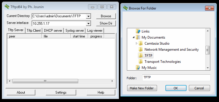
Now what we'll need to do is copy the configuration from flash to TFTP. But first we need to tell the TFTP server where to store the files, essentially we need to give it a directory to download to and upload from. Click browse and navigate to the appropriate file. The Show Dir will show the contents of that folder.


R1#copy flash:iosxe-remote-mgmt.03.15.00.S.155-2.S-std.ova tftp:
Address or name of remote host []? 10.255.1.17
Destination filename [iosxe-remote-mgmt.03.15.00.S.155-2.S-std.ova]


The file is now being downloaded to the TFTP server as a potential backup. In this case, I don't need the file, this was for demo purposes, but you can see that you can download any file from flash or upload a file to flash. Like a new or backup IOS image. I often will keep the IPBase or other vanilla IOS image in flash, if space permits, and then upload the IOS image I intend to use and keep them both in flash.

If you accidentally choose the wrong interface or directory on your TFTP server, the network device will display the following, it's not a dead giveaway why the transfer failed but it's 1 possibility.

R1#copy flash:CCNPSP.conf tftp:
Address or name of remote host []? 10.255.1.17
Destination filename [CCNPSP.conf]?
%Error opening tftp://10.255.1.17/CCNPSP.conf (Permission denied)

Now we'll fix the interface and the directory on the TFTP server and download the configuration file.

R1#copy flash:CCNPSP.conf tftp:
Address or name of remote host []? 10.255.1.17                
Destination filename [CCNPSP.conf]?
!!
1465 bytes copied in 0.101 secs (14505 bytes/sec)

Now we'll upload the config file, essentially just reversing the process.

R1#copy tftp:CCNPSP.conf flash:
Address or name of remote host []? 10.255.1.17
Destination filename [CCNPSP.conf]?
%Warning:There is a file already existing with this name
Do you want to over write? [confirm]
Accessing tftp://10.255.1.17/CCNPSP.conf...
Loading CCNPSP.conf from 10.255.1.17 (via GigabitEthernet1): !
[OK - 1465 bytes]

1465 bytes copied in 0.067 secs (21866 bytes/sec)

And That is really it.

Thanks for reading!

Rob Riker, CCIE #50693


Saving your IOS configuration in Flash rather than the Start up Configuration

Most people that need to save their configuration use "wr mem" or "copy run start" and go about their way. That works and is a classic way to save your config. But for those of us that are not in the set it and forget it mode and need to modify configs on a regular basis, like CCNA prep for instance. We have this nifty configuration option, the "copy run flash:FILENAME.conf".

This gives the ability to save the current configuration in flash but not in the start up configuration. The benefit is that when you need to learn something new or your just getting bored with learning BGP, you can save your config's with "copy run flash:FILENAME.conf" and reload the box. This works on both Routers and Switches of the physical kind, in VIRL and with VMs like CSR1000v and IOS-XRv in ESXi.

When you want to load a saved configuration you can use the "configuration replace flash:FILENAME.conf, answer yes and your saved configuration is loaded!

So how does it work? Simple!

R1#copy run flash:CCNPSP.conf < enter key
Destination filename [CCNPSP.conf]? < enter key
%Warning:There is a file already existing with this name
Do you want to over write? [confirm] < enter key
1463 bytes copied in 0.166 secs (8813 bytes/sec)

R1#dir
Directory of bootflash:/
   20  -rw-             1463  Mar 29 2016 22:23:45 +00:00  CCNPSP.conf

R1#more flash:CCNPSP.conf < will display a text output of the saved configuration file

version 15.5
service timestamps debug datetime msec
service timestamps log datetime msec
no platform punt-keepalive disable-kernel-core
platform console serial
!
hostname R1
!
< output deleted for brevity>

Now, you can reload your device and rest safely knowing that your hard work has not been lost. OK, now your device is backup, or maybe it was power cycled when you were working on something else, processes hang and stuff happens. Not to worry, lets load the that file up!

R1#configure replace flash:CCNPSP.conf < This will replace the running configuration with the saved file in flash!

This will apply all necessary additions and deletions
to replace the current running configuration with the
contents of the specified configuration file, which is
assumed to be a complete configuration, not a partial
configuration. Enter Y if you are sure you want to proceed. ? [no]: yes
Total number of passes: 0
Rollback Done

R1#
*Mar 29 22:29:30.499: Rollback:Acquired Configuration lock.

And there you have it. Your previously saved configurations are now loaded to the running configuration. Your limit of saved files is how much space is available in flash.

R1#dir
Directory of bootflash:/
<output deleted for brevity>
7835619328 bytes total (6516903936 bytes free)

This is a virtual machine running in ESXi 6.0 so I have about 8 GB HDD space allocated, not running out of room anytime soon!

Thanks for Reading, hope this was helpful and informative for you!

Rob Riker, CCIE #50693


Friday, January 29, 2016

Service Provider technologies on IOS and IOS XR

As I begin my preparation to take on the Service Provider v4 CCIE written and lab exams it became obvious to me that I needed to bring my level of understanding up on IOS XR to where it is with IOS. Starting with IGPs, BGP, MPLS, VRFs, and L3 and L2 Intra AS VPNs. Once I have the same level of efficiency in IOS XR that I do with IOS it is time to move into the SP specific topics. Inter AS L2 and L3 VPNs, Inter Domain Multicast, Quality of Service, MPLS Traffic Engineering. Once those topics are well versed and understood from a theory point of view it is then time to make sure I know how to configure them all off the top of my head.

This blog series is designed for just that. As I tackle each topic, I intend on covering the major topics of each topic, RIP for instance. Forming adjacency, Authentication, Summarization for both IPv4 and IPv6. I know what your thinking, RIP, really????? Yes, this isn't specifically CCIE SPv4, this is covering the technologies on the SPv4 CCIE blueprints but not specifically what you may or may not see on the written or lab exams.

Come join me through this adventure that is the rabbit hole of Service Provider!!!

Thanks,
Rob Riker, CCIE #50693 and VCP5/6-DCV